Kecapekan gara-gara aktifitas di kampus ato di tempat kerja??
hoHohoO...Dont worry,disimi ada obatnya.. Silahkan aja ikuti link dibawah ini untuk mendapatkan film-film box office yang up date
Tiren (Mati Kemaren)
*http://rapidshare.com/files/171781084/TIREN-CD01-WWW.SAMUKU.COM.part1.rar
*http://rapidshare.com/files/171814185/TIREN-CD01-WWW.SAMUKU.COM.part2.rar
*http://rapidshare.com/files/171848106/TIREN-CD01-WWW.SAMUKU.COM.part3.rar
*http://rapidshare.com/files/171900758/TIREN-CD01-WWW.SAMUKU.COM.part4.rar
*http://rapidshare.com/files/171917982/TIREN-CD01-WWW.SAMUKU.COM.part5.rar
*http://rapidshare.com/files/172090755/TIREN-CD02-WWW.SAMUKU.COM.part1.rar
*http://rapidshare.com/files/172124477/TIREN-CD02-WWW.SAMUKU.COM.part2.rar
*http://rapidshare.com/files/172258992/TIREN-CD02-WWW.SAMUKU.COM.part3.rar
*http://rapidshare.com/files/172425032/TIREN-CD02-WWW.SAMUKU.COM.part4.rar
*http://rapidshare.com/files/172224253/TIREN-CD02-WWW.SAMUKU.COM.part5.rar
I’m A legend
http://rapidshare.com/files/79638131/WhatALedgggg._-.Fi3nD.part1.rar
http://rapidshare.com/files/79644855/WhatALedgggg._-.Fi3nD.part2.rar
http://rapidshare.com/files/79652146/WhatALedgggg._-.Fi3nD.part3.rar
http://rapidshare.com/files/79659330/WhatALedgggg._-.Fi3nD.part4.rar
http://rapidshare.com/files/79429375/WhatALedgggg._-.Fi3nD.part5.rar
http://rapidshare.com/files/79436715/WhatALedgggg._-.Fi3nD.part6.rar
http://rapidshare.com/files/79442713/WhatALedgggg._-.Fi3nD.part7.rar
The Hunt Begin
http://rapidshare.com/files/79945766/prey-dvdrip-www.rapidsharelinks.info.avi.001
http://rapidshare.com/files/79946922/prey-dvdrip-www.rapidsharelinks.info.avi.002
http://rapidshare.com/files/79947367/prey-dvdrip-www.rapidsharelinks.info.avi.003
http://rapidshare.com/files/79946590/prey-dvdrip-www.rapidsharelinks.info.avi.004
http://rapidshare.com/files/79947082/prey-dvdrip-www.rapidsharelinks.info.avi.005
http://rapidshare.com/files/79942808/prey-dvdrip-www.rapidsharelinks.info.avi.006
http://rapidshare.com/files/79946034/prey-dvdrip-www.rapidsharelinks.info.avi.007
http://rapidshare.com/files/79927780/prey-dvdrip-www.rapidsharelinks.info.avi.008
Lost in Love
http://rapidshare.com/files/175852863/LostinLove_www.SAMUKU.com_CD01.part1.rar
*http://rapidshare.com/files/175886695/LostinLove_www.SAMUKU.com_CD01.part2.rar
*http://rapidshare.com/files/175922590/LostinLove_www.SAMUKU.com_CD01.part3.rar
*http://rapidshare.com/files/175964774/LostinLove_www.SAMUKU.com_CD01.part4.rar
*http://rapidshare.com/files/175982589/LostinLove_www.SAMUKU.com_CD02.part1.rar
*http://rapidshare.com/files/176000163/LostinLove_www.SAMUKU.com_CD02.part2.rar
*http://rapidshare.com/files/176021059/LostinLove_www.SAMUKU.com_CD02.part3.rar
*http://rapidshare.com/files/176039951/LostinLove_www.SAMUKU.com_CD02.part4.rar
In tHe Name oF Love
CD1
*http://rapidshare.com/files/165372425/In_The_Name_Of_Love_VCD-1_by_setiaden.part1.rar
*http://rapidshare.com/files/165311943/In_The_Name_Of_Love_VCD-1_by_setiaden.part2.rar
*http://rapidshare.com/files/165316659/In_The_Name_Of_Love_VCD-1_by_setiaden.part3.rar
*http://rapidshare.com/files/165321172/In_The_Name_Of_Love_VCD-1_by_setiaden.part4.rar
*http://rapidshare.com/files/165333115/In_The_Name_Of_Love_VCD-1_by_setiaden.part5.rar
*http://rapidshare.com/files/165336612/In_The_Name_Of_Love_VCD-1_by_setiaden.part6.rar
CD2
*http://rapidshare.com/files/165341121/In_The_Name_Of_Love_VCD-2_by_setiaden.part1.rar
*http://rapidshare.com/files/165346881/In_The_Name_Of_Love_VCD-2_by_setiaden.part2.rar
*http://rapidshare.com/files/165351763/In_The_Name_Of_Love_VCD-2_by_setiaden.part3.rar
*http://rapidshare.com/files/165356477/In_The_Name_Of_Love_VCD-2_by_setiaden.part4.rar
*http://rapidshare.com/files/165360966/In_The_Name_Of_Love_VCD-2_by_setiaden.part5.rar
*http://rapidshare.com/files/165361144/In_The_Name_Of_Love_VCD-2_by_setiaden.part6.rar
Pulau hAnTu 2
*http://rapidshare.com/files/162659285/P-H-2.part01.rar
*http://rapidshare.com/files/162659288/P-H-2.part02.rar
*http://rapidshare.com/files/162690234/P-H-2.part03.rar
*http://rapidshare.com/files/162690239/P-H-2.part04.rar
*http://rapidshare.com/files/162722841/P-H-2.part05.rar
*http://rapidshare.com/files/162722842/P-H-2.part06.rar
*http://rapidshare.com/files/162732161/P-H-2.part07.rar
Tapi buKan aku
http://rapidshare.com/files/178187372/Tapi..._Bukan_Aku_cd1_www.SAMUKU.com.part1.rar
http://rapidshare.com/files/178211050/Tapi..._Bukan_Aku_cd1_www.SAMUKU.com.part2.rar
http://rapidshare.com/files/178235372/Tapi..._Bukan_Aku_cd1_www.SAMUKU.com.part3.rar
http://rapidshare.com/files/178254972/Tapi..._Bukan_Aku_cd1_www.SAMUKU.com.part4.rar
http://rapidshare.com/files/178280465/Tapi..._Bukan_Aku_cd2_www.SAMUKU.com.part1.rar
http://rapidshare.com/files/178307800/Tapi..._Bukan_Aku_cd2_www.SAMUKU.com.part2.rar
http://rapidshare.com/files/178518871/Tapi..._Bukan_Aku_cd2_www.SAMUKU.com.part3.rar
http://rapidshare.com/files/178540888/Tapi..._Bukan_Aku_cd2_www.SAMUKU.com.part4.rar
http://rapidshare.com/files/178313498/Tapi..._Bukan_Aku_cd2_www.SAMUKU.com.part5.rar
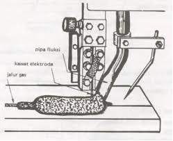
LAS MIG merupakan teknologi yang lumayan baru di Indonesia. Pengelasan jenis ini membutuhkan ketelitian dan kepresisian yang tinggi. Hal ini akan sebanding dengan hasil lasan yang diperoleh.Harga alatnya juga lumayan mahal (bila dibandingkan dengan alat untuk las karbit pinggir jalan :z )
MIG / MAG Welding
Solid wire MIG welding
Metal inert gas (MIG) welding was first patented in the USA in 1949 for welding aluminium. The arc and weld pool formed using a bare wire electrode was protected by helium gas, readily available at that time. From about 1952 the process became popular in the UK for welding aluminium using argon as the shielding gas, and for carbon steels using CO 2 . CO 2 and argon-CO 2 mixtures are known as metal active gas (MAG) processes. MIG is an attractive alternative to MMA, offering high deposition rates and high productivity.
Process characteristics
MIG is similar to MMA in that heat for welding is produced by forming an arc between a metal electrode and the workpiece; the electrode melts to form the weld bead. The main differences are that the metal electrode is a small diameter wire fed from a spool and an externally supplied shielding gas is necessary. As the wire is continuously fed, the process is often referred to as semi-automatic welding.
Metal transfer mode
The manner, or mode, in which the metal transfers from the electrode to the weld pool largely determines the operating features of the process. There are three principal metal transfer modes: 1. Short circuiting 2. Droplet / spray 3. Pulsed
Short-circuiting and pulsed metal transfer are used for low current operation while spray metal transfer is only used with high welding currents. In short-circuiting or'dip' transfer, the molten metal forming on the tip of the wire is transferred by the wire dipping into the weld pool. This is achieved by setting a low voltage; for a 1.2mm diameter wire, arc voltage varies from about 17V (100A) to 22V (200A). Care in setting the voltage and the inductance in relation to the wire feed speed is essential to minimise spatter. Inductance is used to control the surge in current which occurs when the wire dips into the weld pool.
For droplet or spray transfer, a much higher voltage is necessary to ensure that the wire does not make contact i.e.short-circuit, with the weld pool; for a 1.2mm diameter wire, the arc voltage varies from approximately 27V (250A) to 35V (400A). The molten metal at the tip of the wire transfers to the weld pool in the form of a spray of small droplets (about the diameter of the wire and smaller). However, there is a minimum current level, threshold, below which droplets are not forcibly projected across the arc. If an open arc technique is attempted much below the threshold current level, the low arc forces would be insufficient to prevent large droplets forming at the tip of the wire. These droplets would transfer erratically across the arc under normal gravitational forces. The pulsed mode was developed as a means of stabilising the open arc at low current levels i.e. below the threshold level, to avoid short-circuiting and spatter. Metal transfer is achieved by applying pulses of current, each pulse having sufficient force to detach a droplet. Synergic pulsed MIG refers to a special type of controller which enables the power source to be tuned (pulse parameters) for the wire composition and diameter, and the pulse frequency to be set according to the wire feed speed.
Shielding gas
In addition to general shielding of the arc and the weld pool, the shielding gas performs a number of important functions: • forms the arc plasma • stabilises the arc roots on the material surface • ensures smooth transfer of molten droplets from the wire to the weld pool
Thus, the shielding gas will have a substantial effect on the stability of the arc and metal transfer and the behaviour of the weld pool, in particular, its penetration. General purpose shielding gases for MIG welding are mixtures of argon, oxygen and CO 2 , and special gas mixtures may contain helium. The gases which are normally used for the various materials are:
steels CO 2 argon +2 to 5% oxygen argon +5 to 25% CO 2 non-ferrous argon argon / helium
Argon based gases, compared with CO 2 , are generally more tolerant to parameter settings and generate lower spatter levels with the dip transfer mode. However, there is a greater risk of lack of fusion defects because these gases are colder. As CO 2 cannot be used in the open arc (pulsed or spray transfer) modes due to high back-plasma forces, argon based gases containing oxygen or CO 2 are normally employed.
Applications
MIG is widely used in most industry sectors and accounts for more than 50% of all weld metal deposited. Compared to MMA, MIG has the advantage in terms of flexibility, deposition rates and suitability for mechanisation. However, it should be noted that while MIG is ideal for 'squirting' metal, a high degree of manipulative skill is demanded of the welder.
Here is some information about welding metallurgy. I hope you enjoy this one...
Aku dapat materi ini sewaktu berkunjung (sebenarnya sih lebih k jalan-jalan daripada berkunjung ;) ). Jadi jika mau ngopi mohon sekiranya dipergunakan dengan baik dan benar ya. Aku g ingin kamu mendapat karma gara-gara daku yang hina ini..hehehe
Dan akhirnya monggo dinikmati dan sugeng berkreasi untuk kemajuan las di Indonesia..
Ooiya ada yang lupa,silahkan di perbanyak jika diperlukan..Absolutelly Free..
Figure 8.3 Variation in growth rate along pool boundary.
welding
speed, V
weld pool
centerline (CL)
fusion line (FL)
GFL
RCL=V
GCL
R FL 0
G
Tmax
TL ≈
Figure 8.4 Variations in temperature gradient G and growth rate R along pool
boundary.
because the weld pool is elongated. Consequently, the temperature gradient
normal to the pool boundary at the centerline, GCL, is less than that at the
fusion line, GFL. Since GCL < GFL and RCL >> RFL,
(8.4)
8.1.2 Variations in Growth Mode across Weld
According to Equation (8.4), the ratio G/R decreases from the fusion line
toward the centerline. This suggests that the solidification mode may change
from planar to cellular, columnar dendritic, and equiaxed dendritic across the
fusion zone, as depicted in Figure 8.5. Three grains are shown to grow epitaxially
from the fusion line. Consider the one on the right. It grows with the
planar mode along the easy-growth direction <100> of the base-metal grain.
A short distance away from the fusion line, solidification changes to the
cellular mode. Further away from the fusion line, solidification changes to
the columnar dendritic mode. Some of the cells evolve into dendrites and
their side arms block off the neighboring cells. Near the weld centerline
equiaxed dendrites nucleate and grow, blocking off the columnar dendrites.
The solidification-mode transitions have been observed in several different
materials (2–4).
Figure 8.6 shows the planar-to-cellular transition near the weld fusion line
of an autogenous gas–tungsten weld of Fe–49Ni (2). Figure 8.7 shows the
planar-to-cellular transition and the cellular-to-dendritic transition in 1100 aluminum
(essentially pure Al) welded with a 4047 (Al–12Si) filler metal. Figure
8.8 shows the transition from columnar to equiaxed dendrites in an electron
beam weld of a Fe–15Cr–15Ni single crystal containing some sulfur (4).These
columnar dendrites, with hardly visible side arms, follow the easy-growth
G
R
G
R
ÊË
ˆ¯
<<Êˈ¯CL FL202 WELD METAL SOLIDIFICATION II: MICROSTRUCTURE WITHIN GRAINScolumnardendriticplanarcellularequiaxeddendriticweldpoolweldingdirectionbasemetal<100>
<100> <100>
pool
boundary
fusion
line
centerline
Figure 8.5 Variation in solidification mode across the fusion zone.
direction <100> of the single crystal, which happens to be normal to the fusion
line in this case.
Before leaving the subject of the solidification mode, it is desirable to
further consider the weld metal microstructure of a workpiece with only one
and very large grain, that is, a single-crystal workpiece. Figure 8.9 shows the
columnar dendritic structure in a Fe–15Cr–15Ni single crystal of high purity
electron beam welded along a [110] direction on a (001) surface (5).The weld
is still a single crystal because of epitaxial growth. However, it can have
SOLIDIFICATION MODES 203
region of
planar growth
region of
cellular
growth
fusion
line
solidified
weld metal
100 weld pool
boundary
liquid weld
metal
Figure 8.6 Planar-to-cellular transition in an autogenous weld of Fe–49Ni. Modified
from Savage et al. (2).
Figure 8.7 Planar-to-cellular and cellular-to-dendritic transitions in 1100 Al welded
with 4047 filler.
204 WELD METAL SOLIDIFICATION II: MICROSTRUCTURE WITHIN GRAINS
Figure 8.8 Electron beam weld of single crystal of Fe–15Cr–15Ni with sulfur showing
transition from columnar to equiaxed dendrites. Reprinted from David and Vitek (4).
colonies of columnar dendrites of different orientations, as shown by the top
weld pass in Figure 8.9b (f is one of the angles characterizing the normal to
the pool boundary). This is because of competitive growth between columnar
dendrites along the three <100> easy-growth directions [100], [010], and [001].
Dendrites with an easy-growth direction closest to the heat flow direction
(normal to the pool boundary) compete better.
8.2 DENDRITE AND CELL SPACING
The spacing between dendrite arms or cells, just as the solidification mode, can
also vary across the fusion zone. As already mentioned in the previous section,
GCL < GFL and RCL >> RFL. Consequently,
(8.5)
where G ¥ R is the cooling rate, as explained previously in Chapter 6. According
to Equation (8.5), the cooling rate (G ¥ R) is higher at the weld centerline
and lower at the fusion line. This suggests that the dendrite arm spacing
decreases from the fusion line to the centerline because the dendrite arm
spacing decreases with increasing cooling rate (Chapter 6).
The variation in the dendrite arm spacing across the fusion zone can be
further explained with the help of thermal cycles (Chapter 2). Figure 8.10
(G¥R) >(G¥R) CL FL
shows a eutectic-type phase diagram and the thermal cycles at the weld centerline
and fusion line of alloy C0. As shown, the cooling time through the
solidification temperature range is shorter at the weld centerline (2¯4/V) and
longer at the fusion line (1¯3/V). As such, the cooling rate through the solidification
temperature range increases and the dendrite arm spacing decreases
from the fusion line to the centerline. As shown by the aluminum weld in
DENDRITE AND CELL SPACING 205
Figure 8.9 Electron beam weld of single crystal of pure Fe–15Cr–15Ni made in a [110]
direction on a (001) surface: (a) top cross section; (b) transverse cross section.
Reprinted from Rappaz et al. (5).
Figure 8.11, the solidification microstructure gets finer from the fusion line to
the centerline (6). The same trend was observed in other aluminum welds by
Kou et al. (6, 7) and Lanzafame and Kattamis (8).
8.3 EFFECT OF WELDING PARAMETERS
8.3.1 Solidification Mode
The heat input and the welding speed can affect the solidification mode of the
weld metal significantly. The solidification mode changes from planar to cel-
206 WELD METAL SOLIDIFICATION II: MICROSTRUCTURE WITHIN GRAINS
distance
time
T
1 2
3 4
a
b
3
1
2
4
Concentration, C
TL
TE
(a)
(b)
(c)
welding direction
shorter solidification
time, b, at centerline
fusion line
(coarser
microstructure)
A
Temperature, T
L
S
S + L
TL
Co
TE
centerline (finer
microstructure)
longer solidification
time, a, at fusion line
weld
pool
Figure 8.10 Variation in dendrite arm spacing across fusion zone: (a) phase diagram;
(b) thermal cycles; (c) top view of weld pool.
Figure 8.11 Transverse cross-section of gas–tungsten arc weld in 6061 aluminum:
(a) finer microstructure near centerline; (b) coarser microstructure near fusion line.
Magnification 115¥. Reprinted from Kou et al. (6). Courtesy of American Welding
Society.
lular and dendritic as the ratio G/R decreases (Chapter 6). Table 8.1 summarizes
the observations of Savage et al. (9) in HY-80 steel. At the welding speed
of 0.85mm/s (2ipm), the weld microstructure changes from cellular to dendritic
when the welding current increases from 150 to 450A. According to
Equation (2.15), the higher the heat input (Q) under the same welding speed
(V), the lower the temperature gradient G and hence the lower the ratio G/R.
Therefore, at higher heat inputs G/R is lower and dendritic solidification prevails,
while at lower heat inputs G/R is higher and cellular solidification prevails.
Although analytical equations such as Equations (2.15) and (2.17) are
oversimplified, they can still qualitatively tell the effect of welding parameters.
8.3.2 Dendrite and Cell Spacing
The heat input and the welding speed can also affect the spacing between dendrite
arms and cells. The dendrite arm spacing or cell spacing decreases with
increasing cooling rate (Chapter 6). As compared to arc welding, the cooling
rate in laser or electron beam welding is higher and the weld metal microstructure
is finer. The 6061 aluminum welds in Figure 8.12 confirm that this is the
case (10).
As shown in Table 8.1, at the welding current of 150A, the cells become
finer as the welding speed increases. From Equation (2.17), under the same
heat input (Q), the cooling rate increases with increasing welding speed V.
Therefore, at higher welding speeds the cooling rate is higher and the cells are
finer, while at lower welding speeds the cooling rate is lower and the cells are
coarser. Elmer et al. (11) also observed this trend in EBW of two austenitic
stainless steels of similar compositions, as shown in Figure 8.13.The difference
in the cell spacing can be seen even though the magnifications of the micrographs
are different.
According to Equation (2.17), the cooling rate increases with decreasing
heat input–welding speed ratio Q/V. This ratio also represents the amount
EFFECT OF WELDING PARAMETERS 207
TABLE 8.1 Effect of Welding Parameters on Weld Metal Microstructure
Travel speed 150A 300A 450A
0.85mm/s Cellular Cellular dendritic Coarse cellular
(2ipm) dendritic
1.69mm/s Cellular Fine cellular Coarse cellular
(4ipm) dendritic dendritic
3.39mm/s Fine cellular Cellular, slight Severe undercutting
(8ipm) undercutting
6.77mm/s Very fine cellular Cellular, Severe undercutting
(16ipm) undercutting
Source: From Savage et al. (9).
208 WELD METAL SOLIDIFICATION II: MICROSTRUCTURE WITHIN GRAINS
Figure 8.12 Autogenous welds of 6061 aluminum: (a) coarser solidification structure
in gas–tungsten arc weld: (b) finer solidification structure in electron beam weld.
Reprinted from Metals Handbook (10).
Figure 8.13 Effect of welding speed on cell spacing in EBW of austenitic stainless
steels: (a) 100mm/s; (b) 25mm/s. From Elmer et al. (11).
of heat per unit length of the weld (J/cm or cal/cm). Therefore, the dendrite
arm spacing or cell spacing can be expected to increase with increasing
Q/V or amount of heat per unit length of the weld. This has been observed
in several aluminum alloys (7, 8, 12–14), including those shown in Figure
8.14.
8.4 REFINING MICROSTRUCTURE WITHIN GRAINS
It has been shown in aluminum alloys that the finer the dendrite arm spacing,
the higher the ductility (15) and yield strength (8, 15) of the weld metal and
the more effective the postweld heat treatment (8, 12, 15), due to the finer
distribution of interdendritic eutectics.
REFINING MICROSTRUCTURE WITHIN GRAINS 209
10 20 30 40
10
20
(Heat input/welding speed, W/mm)1/2
Dendrite arm spacing, m
30 60 90
(Heat input/welding speed, J/mm)1/2
(b)
(a)
just above toe of weld
level with surface of plate
14
12
10
8
6
4
2
0 10 20 30 40 50 60 70 80
Dendrite spacing, m
Heat input cal/cm length
0
0
μ μ
Figure 8.14 Effect of heat input per unit length of weld on dendrite arm spacing.
(a) For Al–Mg–Mn alloy. From Jordan and Coleman (13). (b) For 2014 Al–Cu alloy.
Modified from Lanzafame and Kattamis (14). Courtesy of American Welding Society.
8.4.1 Arc Oscillation
Kou and Le (16) studied the microstructure in oscillated arc welds of 2014 aluminum
alloy. It was observed that the dendrite arm spacing was reduced significantly
by transverse arc oscillation at low frequencies, as shown in Figure
8.15. This reduction in the dendrite arm spacing has contributed to the significant
improvement in both the strength and ductility of the weld, as shown in
Figure 8.16.
As illustrated in Figure 8.17, when arc oscillation is applied, the weld pool
gains a lateral velocity, v, in addition to its original velocity u in the welding
direction (16). The magnitude of v can be comparable with that of u depending
on the amplitude and frequency of arc oscillation.
As shown, the resultant velocity of the weld pool, w, is greater than that of
the unoscillated weld pool, u. Furthermore, the temperature gradient ahead
of the solid–liquid interface, G, could also be increased due to the smaller
distance between the heat source and the pool boundary. Consequently, the
product GR or the cooling rate is increased significantly by the action of arc
oscillation. This explains why the microstructure is finer in the oscillated arc
weld.
Example: Suppose the welding speed of a regular weld is 4.2mm/s (10ipm).
Calculate the increase in the velocity of the weld pool if the arc is oscillated
210 WELD METAL SOLIDIFICATION II: MICROSTRUCTURE WITHIN GRAINS
NO
OSCILLATION
TRANSVERSE
OSCILLATION
(a) (b)
Figure 8.15 Microstructures near fusion line of gas-tungsten arc welds of 2014 aluminum:
(a) coarser dendrites in weld made without arc oscillation; (b) finer dendrites
in weld made with transverse arc oscillation. Magnification 200¥. Reprinted from Kou
and Le (16). Courtesy of American Welding Society.
transversely at a frequency of 1 Hz and an amplitude (the maximum deflection
of the arc from the weld centerline) of 1.9mm. Do you expect the dendrite
arm spacing to keep on decreasing if the frequency keeps on increasing
to, say, 100Hz?
REFINING MICROSTRUCTURE WITHIN GRAINS 211
Figure 8.16 Tensile testing of two gas–tungsten arc welds of 2014 aluminum made
without arc oscillation and with transverse arc oscillation. From Kou and Le (16).
No
oscillation
u
w v
u
(a)
(b)
Transverse
oscillation
Figure 8.17 Increase in weld pool travel speed due to transverse arc oscillation. Modified
from Kou and Le (16). Courtesy of American Welding Society.
Since the arc travels a distance equal to four oscillation amplitudes
per second, v = 4 ¥ 1.9mm/s = 7.6mm/s. Therefore, the resultant velocity w =
(u2 + v2)1/2 = (4.22 + 7.62)1/2 = 8.7mm/s. The increase in the weld pool velocity
is 8.7 - 4.2 = 4.5mm/s. The increase in the weld pool velocity and hence the
decrease in the dendrite arm spacing cannot keep on going with increasing
oscillation frequency. This is because when the arc oscillates too fast, say at
100 Hz, the weld pool cannot catch up with it because there is not enough time
for melting and solidification to occur.
It is interesting to point out that Kou and Le (16) also observed that the
microstructure in oscillated arc welds is much more uniform than that in welds
without oscillation. In oscillated arc welds the weld centerline is no longer a
location where the cooling rate (or GR) is clearly at its maximum.
Tseng and Savage (17) studied the microstructure in gas–tungsten arc
welds of HY-80 steel made with transverse and longitudinal arc oscillation.
Refining of the grain structure was not obtained, but refining of the dendritic
structure within grains (subgrain structure) was observed and solidification
cracking was reduced, as shown in Figure 8.18. It is possible that solidification
cracking was reduced because the crack-causing constituents were diluted
to a greater extent by the larger interdendritic area in the welds with a finer
dendritic structure.
212 WELD METAL SOLIDIFICATION II: MICROSTRUCTURE WITHIN GRAINS
Half-amplitude =
1.65mm (0.065in)
0 0.23 0.42 1.20
0
10
20
30
Frequency of oscillation-Hz
Subgrain diameter
(microns)
Oscillation frequency
Amplitude =1.65mm
(0.065in)
No
oscillation
0.42
Hz
1.19
Hz
Mean maximum
crack length (mm)
0
0.25
0.50
0.75
Mean maximum
crack length (mils)
0
10
20
30
(a)
(b)
Figure 8.18 Effect of magnetic arc oscillation on gas–tungsten arc welds of HY-80
steel: (a) refining of microstructure within grains; (b) solidification cracking. Modified
from Tseng and Savage (17).
8.4.2 Arc Pulsation
Becker and Adams (18) studied the microstructure in pulsed arc welds of
titanium alloys. It was observed that the cell spacing varied periodically
along the weld, larger where solidification took place during the high-current
portion of the cycle. Obviously, the cooling rate was significantly lower during
the high-current portion of the cycle. This is because, from Equation
(2.17), the cooling rate can be expected to decrease with increasing heat
input, though, strictly speaking, this equation is for steady-state conditions
only.
REFERENCES
1. Nakagawa, H., et al., J. Jpn.Weld. Soc., 39: 94, 1970.
2. Savage,W. F., Nippes, E. F., and Erickson, J. S., Weld. J., 55: 213s, 1976.
3. Kou, S., and Le,Y., unpublished research, University of Wisconsin, Madison, 1983.
4. David, S. A., and Vitek, J. M., Int. Mater. Rev., 34: 213, 1989.
5. Rappaz, M., David, S. A., Vitek, J. M., and Boatner, L. A., in Recent Trends in
Welding Science and Technology, Eds. S. A. David and J. M. Vitek, ASM International,
Materials Park, OH, May 1989, p. 147.
6. Kou, S., Kanevsky, T., and Fyfitch, S., Weld. J., 61: 175s, 1982.
7. Kou, S., and Le,Y., Metall. Trans. A, 14A: 2245, 1983.
8. Lanzafame, J. N., and Kattamis, T. Z., Weld. J., 52: 226s, 1973.
9. Savage,W. F., Lundin, C. D., and Hrubec, R. J., Weld. J., 47: 420s, 1968.
10. Metals Handbook, Vol. 7, 8th ed., American Society for Metals, Metals Park, OH,
1972, pp. 266, 269.
11. Elmer, J.W., Allen, S. M., and Eagar, T.W., Metall. Trans., 20A: 2117, 1989.
12. Brown, P. E., and Adams, C. M. Jr., Weld. J., 39: 520s, 1960.
13. Jordan, M. F., and Coleman, M. C., Br.Weld. J., 15: 552, 1968.
14. Lanzafame, J. N., and Kattamis, T. Z., Weld. J., 52: 226s, 1973.
15. Fukui, T., and Namba, K., Trans. Jpn.Weld. Soc., 4: 49, 1973.
16. Kou, S., and Le,Y., Weld. J., 64: 51, 1985.
17. Tseng, C., and Savage,W. F., Weld. J., 50: 777, 1971.
18. Becker, D.W., and Adams, C. M. Jr., Weld. J., 58: 143s, 1979.
19. Savage, W. F., in Weldments: Physical Metallurgy and Failure Phenomena, Eds.
R. J. Christoffel, E. F. Nippes, and H. D. Solomon, General Electric Co., Schenectady,
NY, 1979, p. 1.
FURTHER READING
1. Davies, G. J., and Garland, J. G., Int. Metall. Rev., 20: 83, 1975.
2. Savage,W. F., Weld.World, 18: 89, 1980.
FURTHER READING 213
3. David, S. A., and Vitek, J. M., Int. Mater. Rev., 34: 213, 1989.
4. Flemings, M. C., Solidification Processing, McGraw-Hill, New York, 1974.
PROBLEMS
8.1 It has been suggested that the secondary dendrite arm spacing d along
the weld centerline can be related quantitatively to the heat input per
unit length of weld, Q/V. Based on the data of the dendrite arm spacing
d as a function of cooling rate e, similar to those shown in Figure 6.17a,
it can be shown that d = ae-1/b, where a and b are constant with b being
in the range of 2–3. (a) Express the dendrite arm spacing in terms of Q/V
for bead-on-plate welds in thick-section aluminum alloys. (b) How do
the preheat temperature and thermal conductivity affect the dendrite
arm spacing? (c) Do you expect the relationship obtained to be very
accurate?
8.2 The size of the mushy zone is often an interesting piece of information
for studying weld metal solidification. Let d = ae-1/b, where d is the dendrite
arm spacing and e the cooling rate. Consider how measurements of
the dendrite arm spacing across the weld metal can help determine
the size of the mushy zone. Express the width of the mushy zone in the
welding direction Dx, as shown in Figure P8.2, in terms of the dendrite
arm spacing d, the welding speed V, and the freezing temperature range
DT (= TL - TE).
8.3 It has been observed that the greater the heat input per unit length of
weld (Q/V), the longer it takes to homogenize the microsegregation in
the weld metal of aluminum alloys for improving its mechanical properties.
Let d = ae-1/b, where d is the dendrite arm spacing and e the cooling
rate. Express the time required for homogenization (t) in terms of Q/V.
8.4 An Al–1% Cu alloy is welded autogenously by GTAW, and an Al–5%
Cu alloy is welded under identical condition.Which alloy is expected to
develop more constitutional supercooling and why? Which alloy is likely
to have more equiaxed dendrites in the weld metal and why?
8.5 An Al–5% Cu alloy is welded autogenously by GTAW and by EBW
under the same welding speed but different heat inputs (much less in the
214 WELD METAL SOLIDIFICATION II: MICROSTRUCTURE WITHIN GRAINS
V
mushy zone
TE
weld pool
TL Δx
Figure P8.2
case of EBW).Which weld is expected to experience more constitutional
supercooling and why? Which weld is likely to have more equiaxed dendrites
and why?
8.6 In autogenous GTAW of aluminum alloys, how do you expect the amount
of equiaxed grains in the weld metal to be affected by preheating and
why?
8.7 In autogenous GTAW of aluminum alloys, how do you expect the dendrite
arm spacing of the weld metal to be affected by preheating and
why?
8.8 Figure P8.8 is a micrograph near the fusion line of an autogenous
gas–tungsten arc weld in a Fe–49% Ni alloy sheet (19). Explain the solidification
microstructure, which is to the right of the fusion line (dark vertical
line).
PROBLEMS 215
Figure P8.8
9 Post-Solidification Phase
Transformations
Post-solidification phase transformations, when they occur, can change the
solidification microstructure and properties of the weld metal. It is, therefore,
essential that post-solidification phase transformations be understood
in order to understand the weld metal microstructure and properties. In
this chapter two major types of post-solidification phase transformations in
the weld metal will be discussed. The first involves the ferrite-to-austenite
transformation in welds of austenitic stainless steels, and the second involves
the austenite-to-ferrite transformation in welds of low-carbon, low-alloy
steels.
9.1 FERRITE-TO-AUSTENITE TRANSFORMATION IN
AUSTENITIC STAINLESS STEEL WELDS
9.1.1 Primary Solidification Modes
The welds of austenitic stainless steels normally have an austenite (fcc) matrix
with varying amounts of d-ferrite (bcc) (1–7). A proper amount of d-ferrite in
austenitic stainless steel welds is essential—too much d-ferrite (10 vol %)
tends to reduce the ductility, toughness, and corrosion resistance, while too
little d-ferrite (5 vol %) can result in solidification cracking.
A. Phase Diagram Figure 9.1 shows the ternary phase diagram of the
Fe–Cr–Ni system (8). The heavy curved line in Figure 9.1a represents the
trough on the liquidus surface, which is called the line of twofold saturation.
The line declines from the binary Fe–Ni peritectic reaction temperature
to the ternary eutectic point at 49Cr–43Ni–8Fe. Alloys with a composition on
the Cr-rich (upper) side of this line have d-ferrite as the primary solidification
phase, that is, the first solid phase to form from the liquid. On the other hand,
alloys with a composition on the Ni-rich (lower) side have austenite as the
primary solidification phase. The heavy curved 1ines on the solidus surface in
Figure 9.1b more or less follow the trend of the liquidus trough and converge
at the ternary eutectic temperature.
The development of weld metal microstructure in austenitic stainless steels
is explained in Figure 9.2.The weld metal ferrite can have three different types
216
Welding Metallurgy, Second Edition. Sindo Kou
Copyright �� 2003 John Wiley & Sons, Inc.
ISBN: 0-471-43491-4
Figure 9.1 The Fe–Cr–Ni ternary system: (
a) liquidus surface; (
b) solidus surface. Reprinted from Metals Handbook (8).
217
218 POST-SOLIDIFICATION PHASE TRANSFORMATIONS
of morphology: interdendritic (Figure 9.2a), vermicular (Figure 9.2b), and
lathy (Figure 9.2c). Figure 9.2d shows a schematic vertical (isoplethal) section
of the ternary phase diagram in Figure 9.1, for instance, at 70 wt % Fe and
above 1200°C. This has also been called a pseudo-binary phase diagram. The
apex (point 1) of the three-phase eutectic triangle (L + g + d) corresponds to
the intersection between the vertical section and the heavy curved line in
Figure 9.1a.The two lower corners (points 2 and 3) of the triangle, on the other
hand, correspond to the intersections between the vertical section and the two
heavy curved lines in Figure 9.1b.
B. Primary Austenite For an alloy on the Ni-rich (left-hand) side of the apex
of the three-phase eutectic triangle, austenite (g) is the primary solidification
phase. The light dendrites shown in Figure 9.2a are austenite, while the dark
particles between the primary dendrite arms are the d-ferrite that forms when
interdendritic
ferrite
(a)
vermicular
ferrite
(b)
lathy
ferrite
(c)
liquid liquid liquid
L
Primary austenite
solidification
increasing Ni
increasing Cr
(d)
austenite, ferrite,
L L
Temperature
liquid, L
1
2 3
4
or
Primary ferrite
solidification
γ
γ γ
δ δ
γ
+ γ
+ γ + δ
γ
+ δ
δ + γ δ
Figure 9.2 Schematics showing solidification and postsolidification transformation in
Fe–Cr–Ni welds: (a) interdendritic ferrite; (b) vermicular ferrite; (c) lathy ferrite; (d)
vertical section of ternary-phase diagram at approximately 70% Fe.
the three-phase triangle is reached during the terminal stage of solidification.
These are called the interdendritic ferrite. For dendrites with long secondary
arms, interdendritic ferrite particles can also form between secondary dendrite
arms.
C. Primary Ferrite For an alloy on the Cr-rich (right-hand) side of the apex
of the three-phase eutectic triangle, d-ferrite is the primary solidification phase.
The dark dendrites shown in Figure 9.2b are d-ferrite.The core of the d-ferrite
dendrites, which forms at the beginning of solidification, is richer in Cr (point
4), while the outer portions, which form as temperature decreases, have lower
chromium contents. Upon cooling into the (d + g) two-phase region, the outer
portions of the dendrites having less Cr transform to austenite, thus leaving
behind Cr-rich “skeletons” of d-ferrite at the dendrite cores. This skeletal
ferrite is called vermicular ferrite. In addition to vermicular ferrite, primary
d-ferrite dendrites can also transform to lathy or lacy ferrite upon cooling
into the (d + g) two-phase region, as shown in Figure 9.2c.
D. Weld Microstructure Figure 9.3a shows the solidification structure at the
centerline of an autogenous gas–tungsten arc weld of a 310 stainless steel
sheet, which contains approximately 25% Cr, 20% Ni, and 55% Fe by weight
(9).The composition is on the Ni-rich (left) side of the apex of the three-phase
eutectic triangle, as shown in Figure 9.4a, and solidification occurs as primary
austenite. The microstructure consists of austenite dendrites (light etching;
mixed-acids etchant) and interdendritic d-ferrite (dark etching; mixed-acids
etchant) between the primary and secondary dendrite arms, similar to those
shown in Figure 9.2a.
Figure 9.3b, on the other hand, shows the solidification structure at the
centerline of an autogenous gas–tungsten arc weld of a 309 stainless steel
sheet, which contains approximately 23 wt% Cr, 14 wt% Ni, and 63 wt % Fe.
The composition lies just to the Cr-rich side of the apex of the three-phase
eutectic triangle, as shown in Figure 9.4b, and solidifies as primary d-ferrite.
The microstructure consists of vermicular ferrite (dark etching; mixedacids
etchant) in an austenite matrix (light etching; mixed-acids etchant)
similar to those shown in Figure 9.2b. In both welds columnar dendrites grow
essentially perpendicular to the teardrop-shaped pool boundary as revealed
by the columnar dendrites.
Kou and Le (9) quenched welds during welding in order to preserve
the as-solidified microstructure, that is, the microstructure before postsolidification
phase transformations. For stainless steels liquid-tin quenching
is more effective than water quenching because steam and bubbles reduce heat
transfer.With the help of quenching, the evolution of microstructure during
welding can be better studied. Figure 9.5 shows the d-ferrite dendrites (light
etching; mixed-chloride etchant) near the weld pool of an autogenous gas–
tungsten arc weld of 309 stainless steel, quenched in during welding with liquid
tin before the d Æ g transformation changed it to vermicular ferrite like that
TRANSFORMATION IN AUSTENITIC STAINLESS STEEL WELDS 219
220 POST-SOLIDIFICATION PHASE TRANSFORMATIONS
Figure 9.3 Solidification structure at the weld centerline: (a) 310 stainless steel; (b)
309 stainless steel. Magnification 190¥. Reprinted from Kou and Le (9).
L L L
55%Fe 63%Fe 73%Fe
1400
1000
600
15
30
25
20
35
10
10
27
20
17
30
7
5
22
15
12
25
2
wt%Cr
wt%Ni
Temperature, oC
(a) (b) (c)
L + γ + δ
γ
γ γ
δ
δ
δ
δ + γ
δ
+γδ
+
γ
Figure 9.4 The Fe–Cr–Ni pseudo-binary phase diagrams: (a) at 55 wt % Fe; (b) at 63
wt % Fe; (c) at 73 wt % Fe. Reprinted from Kou and Le (9).
TRANSFORMATION IN AUSTENITIC STAINLESS STEEL WELDS 221
shown in Figure 9.3b. Liquid-tin quenching was subsequently used by other
investigators to study stainless steel welds (10, 11).
9.1.2 Mechanisms of Ferrite Formation
Inoue et al. (11) studied vermicular and lathy ferrite in autogenous GTAW of
austenitic stainless steels of 70% Fe with three different Cr–Ni ratios. It was
found that, as the Cr–Ni ratio increases, the ratio of lathy ferrite to total ferrite
does not change significantly even though both increase. A schematic of the
proposed formation mechanism of vermicular and lathy ferrite is shown in
Figure 9.6.Austenite first grows epitaxially from the unmelted austenite grains
at the fusion boundary, and d-ferrite soon nucleates at the solidification front.
The crystallographic orientation relationship between the d-ferrite and the
austenite determines the ferrite morphology after the postsolidification transformation.
If the closed-packed planes of the d-ferrite are parallel to those of
the austenite, the d Æ g transformation occurs with a planar d/g interface,
resulting in vermicular ferrite. However, if the so-called Kurdjumov–Sachs orientation
relationships, namely, (1¯10)d //(1¯11)g and [1¯1¯1]d //[1¯1¯0]g, exist between
the d-ferrite and the austenite, the transformation occurs along the austenite
habit plane into the d-ferrite dendrites. The resultant ferrite morphology is
lathy, as shown in Figure 9.7. For the lathy ferrite to continue to grow, the
Figure 9.5 Liquid-tin quenched solidification structure near the pool of an autogenous
gas–tungsten arc weld of 309 stainless steel. Magnification 70. Mixed-chloride
etchant. Reprinted from Kou and Le (9).
222 POST-SOLIDIFICATION PHASE TRANSFORMATIONS
Figure 9.6 Mechanism for the formation of vermicular and lathy ferrite. Reprinted
from Inoue et al. (11).
Figure 9.7 Lathy ferrite in an autogenous gas–tungsten arc weld of Fe–18.8Cr–11.2Ni.
Reprinted from Inoue et al. (11).
TRANSFORMATION IN AUSTENITIC STAINLESS STEEL WELDS 223
preferred growth direction <100> of both d-ferrite and austenite must be
aligned with the heat flow direction.
9.1.3 Prediction of Ferrite Content
Schaeffler (12) first proposed the quantitative relationship between the composition
and ferrite content of the weld metal. As shown by the constitution
diagram in Figure 9.8, the chromium equivalent of a given alloy is determined
from the concentrations of ferrite formers Cr, Mo, Si, and Cb, and the austenite
equivalent is determined from the concentrations of austenite formers Ni,
C, and Mn. DeLong (13) refined Schaeffler’s diagram to include nitrogen, a
strong austenite former, as shown in Figure 9.9. Also, the ferrite content is
expressed in terms of the ferrite number, which is more reproducible than the
ferrite percentage and can be determined nondestructively by magnetic
means. Figure 9.10 shows that nitrogen, introduced into the weld metal by
adding various amounts of N2 to the Ar shielding gas, can reduce the weld
ferrite content significantly (14). Cieslak et al. (6), Okagawa et al. (7), and
Lundin et al. (15) have reported similar results previously.
The WRC-1992 diagram of Kotecki and Siewert (16), shown in Figure 9.11,
was from the Welding Research Council in 1992. It was modified from the
WRC-1988 diagram of McCowan et al. (17) by adding to the nickel equivalent
the coefficient for copper (18) and showing how the axes could be
extended to make Schaeffler-like calculations for dissimilar metal joining.
20
30
10
0
10 20 30 40
Chromium equivalent =
%Cr + %Mo + 1.5 X %Si + 0.5 X %Cb
Nickel equivalent =
%Ni + 30 X %C + 0.5 X %Mn
Austenite
0% Ferrite
5%
20%
40%
100%
Ferrite
Martensite
M + F
A + M
0
28
26
24
22
12
14
16
18
8
64
2
2 4 6 8 12141618 2224 26 28 32 34 36 38
F + M
A + M + F
80%
10%
A + F
Figure 9.8 Schaeffler diagram for predicting weld ferrite content and solidification
mode. From Schaeffler (12).
224 POST-SOLIDIFICATION PHASE TRANSFORMATIONS
Kotecki (19, 20) added the martensite boundaries to the WRC-1992 diagram,
as shown in Figure 9.12. More recent investigations of Kotecki (21, 22) have
revealed that the boundaries hold up well with Mo and N variation but
not as well with C variation. Balmforth and Lippold (23) proposed the
ferritic–martensitic constitution diagram shown in Figure 9.13.Vitek et al. (24,
0
4
2
WRC ferrite
number
Austenite
Austenite
plus ferrite
Schaeffler
A + M line
16 17 18 19 21 22 23 24 25 26 27
10
11
12
13
14
15
16
17
18
19
20
21
Chromium equivalent =
%Cr + %Mo + 1.5 X %Si + 0.5 X %Cb
Nickel equivalent =
%Ni + 30 X %C + 30 X %N + 0.5 X %Mn
12
14
16
18
10
6
8
0
2
4
6
7.6
9.2
10.7
12.3
13.820
Prior magnetic ferrite %
Figure 9.9 DeLong diagram for predicting weld ferrite content and solidification
mode. Reprinted from DeLong (13). Courtesy of American Welding Society.
0.1 0.2 0.3 0.4
0
20
40
60
80
Nitrogen content (mass%)
Ferrite content (%)
Figure 9.10 Effect of nitrogen on ferrite content in gas–tungsten arc welds of duplex
stainless steel. Reprinted from Sato et al. (14).
TRANSFORMATION IN AUSTENITIC STAINLESS STEEL WELDS 225
Figure 9.11 WRC-1992 diagram for predicting weld ferrite content and solidification
mode. Reprinted from Kotecki and Siewert (16). Courtesy of American Welding
Society.
Figure 9.12 WRC-1992 diagram with martensite boundaries for 1, 4, and 10% Mn.
Reprinted from Kotecki (20). Courtesy of American Welding Society.
226 POST-SOLIDIFICATION PHASE TRANSFORMATIONS
25) developed a model FNN-1999 using artificial neural networks to improve
ferrite number prediction, as shown in Figure 9.14. Twelve alloying elements
besides Fe were considered: C, Cr, Ni, Mo,N, Mn, Si, Cu,Ti, Cb,V, and Co.The
model is not in a simple pictorial form, such as the WRC-1992 diagram,
because it allows nonlinear effects and element interactions.
9.1.4 Effect of Cooling Rate
A. Changes in Solidification Mode The prediction of the weld metal ferrite
content based on the aforementioned constitution diagrams can be inaccurate
10 30
20 40
50
60 70 80 90
A+M+
F
Cr + 2Mo + 10(Al + Ti)
Ni + 35C + 20N
8 10 12 14 16 18 20 22
0
1
2
3
4
5
6
M + F
Martensite
Ferrite
Figure 9.13 Ferritic–martensitic stainless steel constitution diagram containing a
boundary for austenite formation and with iso-ferrite lines in volume percent of ferrite.
Reprinted from Balmforth and Lippold (23).
Figure 9.14 Experimentally measured ferrite number (FN) versus predicted FN: (a)
FNN-1999; (b) WRC-1992. Reprinted from Vitek et al. (25). Courtesy of American
Welding Society.
TRANSFORMATION IN AUSTENITIC STAINLESS STEEL WELDS 227
when the cooling rate is high, especially in laser and electron beam welding
(3, 26–37). Katayama and Matsunawa (28, 29), David et al. (31), and Brooks
and Thompson (37) have compared microstructures that form in slow-coolingrate
arc welds with those that form in high-cooling-rate, high-energy-beam
welds.Their studies show two interesting trends. For low Cr–Ni ratio alloys the
ferrite content decreases with increasing cooling rate, and for high Cr–Ni ratio
alloys the ferrite content increases with increasing cooling rate. Elmer et al.
(33) pointed out that in general low Cr–Ni ratio alloys solidify with austenite
as the primary phase, and their ferrite content decreases with increasing
cooling rate because solute redistribution during solidification is reduced at
high cooling rates. On the other hand, high Cr–Ni ratio alloys solidify with
ferrite as the primary phase, and their ferrite content increases with increasing
cooling rate because the d Æ g transformation has less time to occur at
high cooling rates.
Elmer et al. (33, 34) studied a series of Fe–Ni–Cr alloys with 59% Fe and
the Cr–Ni ratio ranging from 1.15 to 2.18, as shown in Figure 9.15. The apex
of the three-phase triangle is at about Fe–25Cr–16Ni. Figure 9.16 summarizes
the microstructural morphologies of small welds made by scanning an electron
beam over a wide range of travel speeds and hence cooling rates (33). At
low travel speeds such as 0.1–1mm/s, the cooling rates are low and the alloys
with a low Cr–Ni ratio (especially alloys 1 and 2) solidify as primary austenite.
The solidification mode is either single-phase austenite (A), that is, no
ferrite between austenite dendrites or cells (cellular–dendritic A), or primary
austenite with second-phase ferrite (AF), that is, only a small amount of ferrite
between austenite dendrites (interdendritic F). The alloys with a high Cr–Ni
Cr 21 23 25 27 29 31
A + F
L + A L + F
A F
Composition, wt%
Ni 20 18 16 14 12 10
1 2 3 4 5 6 7
1200
1250
1300
1350
1400
1450
1500
1550
Temperature, oC
L 59% Fe
Figure 9.15 Vertical section of Fe–Ni–Cr phase diagram at 59% Fe showing seven
alloys with Cr–Ni ratio ranging from 1.15 to 2.18. Modified from Elmer et al. (33).
228 POST-SOLIDIFICATION PHASE TRANSFORMATIONS
ratio (especially alloys 5–7), on the other hand, solidify as primary ferrite.The
solidification mode is primary ferrite with second-phase austenite (FA), that
is, vermicular ferrite, lacy ferrite, small blocks of austenite in a ferrite matrix
(blocky A), or Widmanstatten austenite platelets originating from ferrite grain
boundaries (Widmanstatten A).
At very high welding speeds such as 2000mm/s, however, the cooling rates
are high and the alloys solidify in only the single-phase austenite mode (A) or
the single-phase ferrite mode (F). An example of the former is the alloy 3
(about Fe–24.75Cr–16.25Ni) shown in Figure 9.17a. At the travel speed of
25mm/s (2 ¥ 103 °C/s cooling rate) the substrate solidifies as primary austenite
in the AF mode, with austenite cells and intercellular ferrite. At the much
higher travel speed of 2000 mm/s (1.5 ¥ 106 °C/s cooling rate) the weld at the
top solidifies as primary austenite in the A mode, with much smaller austenite
cells and no intercellular ferrite (cellular A). An example of the latter is
alloy 6 (about Fe–27.5Cr–13.5Ni) shown in Figure 9.17b. At 25 mm/s the substrate
solidifies as primary ferrite in the FA mode, with blocky austenite in a
ferrite matrix. At 2000 mm/s the weld at the top solidifies as primary ferrite in
the F mode, with ferrite cells alone and no austenite (cellular F).
Figure 9.16 also demonstrates that under high cooling rates an alloy that
solidifies as primary ferrite at low cooling rates can change to primary austenite
solidification. For instance, alloy 4 (about Fe–25.5Cr–15.5Ni) can solidify
as primary ferrite at low cooling rates (vermicular F) but solidifies as primary
10-1
Widmanstatten A
blocky A
lacy F
vermicular F
intercellular A
interdendritic F intercellular F
cellular-dendritic A
cellular F
massive A
cellular A
100 101 102 103 104
Electron-beam travel speed, mm/s
Composition, wt%
1
2 3
4
5
6
7
Cr
30
28
24
22
20
Ni
11
13
15
17
19
21
26
alloys
Figure 9.16 Electron beam travel speed (cooling rate) versus composition map of
microstructural morphologies of the seven alloys in Figure 9.15 (A and F denote
austenite and ferrite, respectively). The solid lines indicate the regions of the four
primary solidification modes, while the dashed lines represent the different morphologies
resulting from postsolidification transformation from ferrite to austenite. Modified
from Elmer et al. (33).
TRANSFORMATION IN AUSTENITIC STAINLESS STEEL WELDS 229
austenite at higher cooling rates (intercellular F or cellular A). Another interesting
point seen in the same figure is that at high cooling rates alloy 5 can
solidify in the fully ferritic mode and undergoes a massive (diffusionless) transformation
after solidification to austenite (massive A). Under very high
cooling rates there is no time for diffusion to occur.
B. Dendrite Tip Undercooling Vitek et al. (27) attributed the change solidification
mode, from primary ferrite to primary austenite, at high cooling rates
to dendrite tip undercooling. Brooks and Thompson (37) explained this undercooling
effect based on Figure 9.18. Alloy C0 solidifies in the primary ferrite
mode at low cooling rates. Under rapid cooling in laser or electron beam
welding, however, the melt can undercool below the extended austenite
liquidus (CLg), and it becomes thermodynamically possible for the melt to
solidify as primary austenite. The closer C0 is to the apex of the three-phase
triangle, the easier sufficient undercooling can occur to switch the solidification
mode from primary ferrite to primary austenite.
Figure 9.17 Microstructure of the low-cooling-rate substrate (2 ¥ 103 °C/s) and the
high-cooling-rate electron beam weld at the top: (a) alloy 3 in Figure 9.15; (b) alloy 6.
Reprinted from Elmer et al. (34).
230 POST-SOLIDIFICATION PHASE TRANSFORMATIONS
Kou and Le (9) made autogenous gas–tungsten arc welds in 309 stainless
steel, which has a composition close to the apex of the three-phase triangle,
as shown in Figure 9.4b. At 2 mm/s (5 ipm) welding speed, primary ferrite was
observed across the entire weld (similar to that shown in Figure 9.3b). At a
higher welding speed of 5mm/s (12ipm), however, primary austenite was
observed along the centerline, as shown in Figure 9.19. Electron probe microanalysis
(EPMA) revealed no apparent segregation of either Cr or Ni near
the weld centerline to cause the change in the primary solidification phase.
From Equation (8.3) the growth rate R = Vcosa, where a is the angle between
the welding direction and the normal to the pool boundary. Because of the
teardrop shape of the weld pool during welding (Figure 2.22), a drops to zero
Ni
Cr
Temperature
Composition
+ L + L
+
Co
CS CS
CL
CL
δ γ
γ
δ
δ γ
γ
δ
δ γ
Figure 9.18 Vertical section of Fe–Cr–Ni phase diagram showing change in solidification
from ferrite to austenite due to dendrite tip undercooling. Reprinted from
Brooks and Thompson (37).
Figure 9.19 Weld centerline austenite in an autogenous gas–tungsten arc weld of 309
stainless steel solidified as primary ferrite. From Kou and Le (9).
TRANSFORMATION IN AUSTENITIC STAINLESS STEEL WELDS 231
and R increases abruptly at the weld centerline. As such, the cooling rate (GR)
increases abruptly at the weld centerline, as pointed out subsequently by
Lippold (38).
Elmer et al. (34) calculated the dendrite tip undercooling for the alloys in
Figure 9.16 under various electron beam travel speeds. An undercooling of
45.8°C was calculated at the travel speed of 175mm/s, which is sufficient to
depress the dendrite tip temperature below the solidus temperature (Figure
9.15). This helps explain why alloy 4 can change from primary ferrite solidification
at low travel speeds to primary austenite solidification at much higher
travel speeds.
9.1.5 Ferrite Dissolution upon Reheating
Lundin and Chou (39) observed ferrite dissolution in multiple-pass or repair
austenitic stainless steel welds. This region exists in the weld metal of a previous
deposited weld bead, adjacent to but not contiguous with the fusion zone
of the deposited bead under consideration. Both the ferrite number and ductility
are lowered in this region, making it susceptible to fissuring under strain.
This is because of the dissolution of d-ferrite in the region of the weld metal
that is reheated to below the g-solvus temperature. Chen and Chou (40)
reported, in Figure 9.20, a significant ferrite loss in a 316 stainless steel weld
Figure 9.20 Effect of thermal cycles on ferrite content in 316 stainless steel weld: (a)
as welded; (b) subjected to thermal cycle of 1250°C peak temperature three times after
welding. Reprinted from Chen and Chou (40).
232 POST-SOLIDIFICATION PHASE TRANSFORMATIONS
subjected to three postweld thermal cycles with a 1250°C peak temperature,
which is just below the g + d two-phase region of about 1280–1425°C.
9.2 AUSTENITE-TO-FERRITE TRANSFORMATION IN
LOW-CARBON, LOW-ALLOY STEEL WELDS
9.2.1 Microstructure Development
The dendrites or cells in the weld metal are not always discernible. First, significant
solute partitioning does not occur during solidification if the partition
ratio k is too close to 1. The miscrosegregation, especially solute segregation
to the interdendritic or intercellular regions, in the resultant weld metal can
be too little to bring out the dendritic or cellular structure in the grain interior
even though the grain structure itself can still be very clear. Second, if
solid-state diffusion occurs rapidly, microsegregation either is small or is
homogenized quickly, and the dendrites or cells in the resultant weld metal
can be unclear. Third, post-solidification phase transformations, if they occur,
can produce new microstructures in the grain interior and/or along grain
boundaries and the subgrain structure in the resultant weld metal can be
overshadowed.
Several continuous-cooling transformation (CCT) diagrams have been
sketched schematically to explain the development of the weld metal
microstructure of low-carbon, low-alloy steels (41–45). The one shown in
Figure 9.21 is based on that of Onsoien et al. (45).The hexagons represent the
transverse cross sections of columnar austenite grains in the weld metal. As
austenite (g) is cooled down from high temperature, ferrite (a) nucleates at
the grain boundary and grows inward.The grain boundary ferrite is also called
“allotriomorphic” ferrite, meaning that it is a ferrite without a regular faceted
grain boundary ferrite
sideplate ferrite
accicular ferrite
bainite
austenite
grain
log Time
Temperature
inclusion particle
grain boundary
martensite
cooling
curve
austenite
Figure 9.21 Continuous-cooling transformation diagram for weld metal of lowcarbon
steel.
TRANSFORMATION IN LOW-CARBON, LOW-ALLOY STEEL WELDS 233
shape reflecting its internal crystalline structure. At lower temperatures the
mobility of the planar growth front of the grain boundary ferrite decreases
and Widmanstatten ferrite, also called side-plate ferrite, forms instead. These
side plates can grow faster because carbon, instead of piling up at the planar
growth front, is pushed to the sides of the growing tips. Substitutional atoms
do not diffuse during the growth of Widmanstatten ferrite. At even lower temperatures
it is too slow for Widmanstatten ferrite to grow to the grain interior
and it is faster if new ferrite nucleates ahead of the growing ferrite. This new
ferrite, that is, acicular ferrite, nucleates at inclusion particles and has randomly
oriented short ferrite needles with a basket weave feature.
Figure 9.22 shows the microstructure of the weld metal of a low-carbon,
low-alloy steel (46). It includes in Figure 9.22a grain boundary ferrite (A),
Figure 9.22 Micrographs showing typical weld metal microstructures in low-carbon
steels: A, grain boundary ferrite; B, polygonal ferrite; C, Widmanstatten ferrite; D,
acicular ferrite; E, upper bainite; F, lower bainite. Reprinted from Grong and Matlock
(46).
(a)
(b)
234 POST-SOLIDIFICATION PHASE TRANSFORMATIONS
Widmanstatten ferrite (C), and acicular ferrite (D) and in Figure 9.22b
upper bainite (E) and lower bainite (F). A polygonal ferrite (B) is also found.
Examination with transmission electron microscopy (TEM) is usually needed
to identify the upper and lower bainite. The microstructure of a low-carbon
steel weld containing predominately acicular ferrite is shown in Figure 9.23
and at a higher magnification in Figure 9.24 (47). The dark particles are
inclusions.
9.2.2 Factors Affecting Microstructure
Bhadeshia and Suensson (48) showed in Figure 9.25 the effect of several
factors on the development of microstructure of the weld metal: the weld
metal composition, the cooling time from 800 to 500°C (Dt8–5), the weld metal
oxygen content, and the austenite grain size. The vertical arrows indicate the
directions in which these factors increase in strength. This will be explained
with the help of CCT curves.
A. Cooling Time Consider the left CCT curves (broken lines) in Figure 9.26.
As cooling slows down (Dt8–5 increases) from curve 1 to curve 2 and curve 3,
and the transformation product can change from predominately bainite
(Figure 9.25c), to predominately acicular ferrite (Figure 9.25b) to predominately
grain boundary and Widmanstatten ferrite (Figure 9.25a).
Figure 9.23 Predominately acicular ferrite microstructure of a low-carbon, low-alloy
steel weld. Reprinted from Babu et al. (47).
TRANSFORMATION IN LOW-CARBON, LOW-ALLOY STEEL WELDS 235
Figure 9.24 Acicular ferrite and inclusion particles in a low-carbon, low-alloy steel
weld. Reprinted from Babu et al. (47).
Figure 9.25 Schematic showing effect of alloy additions, cooling time from 800 to
500°C, weld oxygen content, and austenite grain size. Reprinted from Bhadeshia and
Svensson (48).
B. Alloying Additions An increase in alloying additions (higher hardenability)
will shift the CCT curves toward longer times and lower temperatures.
Consider now cooling curve 3 in Figure 9.26. The transformation product can
change from predominately grain boundary and Widmanstatten ferrite (left
CCT curves) to predominately acicular ferrite (middle CCT curves) to predominately
bainite (right CCT curves). This is like what Figure 9.25 shows.
236 POST-SOLIDIFICATION PHASE TRANSFORMATIONS
C. Grain Size Similar to the effect of alloying additions, an increase in the
austenite grain size (less grain boundary area for ferrite nucleation) will also
shift the CCT curves toward longer times and lower temperatures.
D. Weld Metal Oxygen Content The effect of the weld metal oxygen
content on the weld metal microstructure is explained as follows. First, as
shown in Figure 9.27, Fleck et al. (49) observed in submerged arc welds that
the austenite grain size before transformation decreases with increasing
weld metal oxygen content. Liu and Olson (50) observed that increasing the
weld metal oxygen content increased the inclusion volume fraction and
decreased the average inclusion size. In fact, a large number of smaller size
inclusions of diameters less than 0.1mm was found. Since fine second-phase
particles are known to increasingly inhibit grain growth by pinning the grain
boundaries as the particles get smaller and more abundant (51), increasing the
weld metal oxygen content should decrease the prior austenite grain size.
1 2 3
grain boundary ferrite
sideplate ferrite
acicular ferrite
bainite
austenite
log Time
Temperature
increasing alloying additions
increasing grain size
decreasing oxygen
Figure 9.26 Effect of alloying elements, grain size, and oxygen on CCT diagrams for
weld metal of low-carbon steel.
Q&T C-Mn-Mo-Nb
plate 3.0 MJ/m welds
Weld metal oxygen content, wt %
0.01 0.02 0.03 0.04 0.05
70
80
90
100
110
Prior austenite grain
diameter, m μ
Figure 9.27 Prior austenite grain diameter as a function of weld metal oxygen content
in submerged arc welds. Reprinted from Fleck et al. (49). Courtesy of American
Welding Society.
TRANSFORMATION IN LOW-CARBON, LOW-ALLOY STEEL WELDS 237
Therefore, the effect of decreasing the weld metal oxygen content is similar to
that of increasing the prior austenite grain size. This is just like what Figure
9.25 shows.
Second, larger inclusions, which are favored by lower weld metal oxygen
contents, can act as favorable nucleation sites for acicular ferrite (50). Appropriate
inclusions appear to be in the size range 0.2–2.0mm, and the mean size
of about 0.4mm has been suggested to be the optimum value (49, 51–53). Fox
et al. (54) suggested in submerged arc welds of HY-100 steel that insufficient
inclusion numbers are generated for the nucleation of acicular ferrite if the
oxygen content is too low (<200ppm). On the other hand, many small oxideinclusions (<0.2mm) can be generated if the oxygen content is too high(>300ppm). These inclusions, though too small to be effective nuclei for acicular
ferrite, reduce the grain size and thus provide much grain boundary area
for nucleation of grain boundary ferrite. As such, an optimum oxygen content
can be expected for acicular ferrite to form.This is just like what Figure 9.25b
shows.
The existence of an optimum oxygen content for acicular ferrite to form
has also been reported by Onsoien et al. (45) in GMAW with oxygen or carbon
dioxide added to argon, as shown clearly in Figure 9.28. With Ar–O2 as the
shielding gas, the shielding gas oxygen equivalent is the volume percentage of
O2 in the shielding gas. With Ar–CO2 as the shielding gas, it becomes the
volume percentage of CO2 in the shielding gas that will produce the same
oxygen content in the weld metal. As expected, the experimental results show
that the higher the shielding gas oxygen equivalent, the more hardenability
elements such as Mn and Si from the filler wire are oxidized. Consider again
cooling curve 3 in Figure 9.26. As the shielding gas oxygen equivalent is
reduced, the CCT curves can shift from left (broken lines) to middle (solid
0 5 10 15 20
0
20
40
60
80
100
Shielding gas oxygen
equivalent (vol. pct.)
Acicular ferrite content (vol. pct.)
ER 70S-3, 1.8 MJ/m
Oxygen in shielding gas
Carbon dioxide in
shielding gas
Figure 9.28 Acicular ferrite content as a function of shielding gas oxygen equivalent
for gas–metal arc welds. Reprinted from Onsoien et al. (45). Courtesy of American
Welding Society.
238 POST-SOLIDIFICATION PHASE TRANSFORMATIONS
lines) and a predominately acicular microstructure is produced. However, as
the shielding gas oxygen equivalent is reduced further, the CCT curves can
shift from middle (solid lines) to right (dotted lines) and acicular ferrite no
longer predominates.
Other factors have also been reported to affect amount of acicular ferrite
in the weld metal. For example, it has been reported that acicular ferrite
increases with increasing basicity index of the flux for submerged arc welding
(54), Ti (55, 56), and Mn and Ni (57).
9.2.3 Weld Metal Toughness
Acicular ferrite is desirable because it improves the toughness of the weld
metal (55, 56). As shown in Figure 9.29, Dallam et al. (57) observed that the
Volume percent acicular ferrite
Energy absorbed (ft-lbs)
Joules
0 30 40 50 60 70 80
10
20
40
30
30
10
20
40
50
Q&T C-Mn-Mo-Nb plate
3.0 MJ/m welds
test temp. -40oC
7.6 X 7.6 mm izod tests
Figure 9.29 Subsize Charpy V-notch toughness values as a function of volume
fraction of acicular ferrite in submerged arc welds. Reprinted from Fleck et al. (49).
Courtesy of American Welding Society.
0 2 4 6 8 10
-60
-50
-40
-30
-20
-10
0
Shielding gas oxygen
equivalent (vol. pct.)
Transition temperature at
35J (deg. C)
Figure 9.30 Weld metal Charpy V-notch toughness expressed as transition temperature
as a function of shielding gas oxygen equivalent. Reprinted from Onsoien et al.
(45). Courtesy of American Welding Society.
REFERENCES 239
weld metal Charpy V-notch toughness in submerged arc welds increases with
increasing volume fraction of acicular ferrite in the weld metal. The interlocking
nature of acicular ferrite, together with its fine grain size, provides the
maximum resistance to crack propagation by cleavage.The formation of grain
boundary ferrite, ferrite side plates, or upper bainite is detrimental to weld
metal toughness, since these microstructures provide easy crack propagation
paths.
Onsoien et al. (45) tested the Charpy V-notch toughness of GMA weld
metal using an energy absorption of 35 J as the criterion for measuring the
transition temperature for ductile-to-brittle fracture. Figure 9.30 showed that
the maximum toughness (minimum transition temperature)occurs at a shielding
gas oxygen equivalent of about 2 vol %. This, as can be seen from Figure
9.28, essentially corresponds to the maximum amount of acicular ferrite in the
weld metal, thus clearly demonstrating the beneficial effect of acicular ferrite
on weld metal toughness. Ahlblom (58) has shown earlier a clear minimum in
the plots of Charpy V-notch transition temperature versus weld metal oxygen
content.
REFERENCES
1. David, S. A., Goodwin, G. M., and Braski, D. N., Weld. J., 58: 330s, 1979.
2. David, S. A., Weld. J., 60: 63s, 1981.
3. Lippold, J. C., and Savage,W. F., Weld. J., 58: 362s, 1974.
4. Lippold, J. C., and Savage,W. F., Weld. J., 59: 48s, 1980.
5. Cieslak, M. J., and Savage,W. F., Weld. J., 59: 136s, 1980.
6. Cieslak, M. J., Ritter, A. M., and Savage,W. F., Weld. J., 62: 1s, 1982.
7. Okagawa, R. K., Dixon, R. D., and Olson, D. L., Weld. J., 62: 204s, 1983.
8. Metals Handbook, Vol. 8, 8th ed., American Society for Metals, Metals Park, OH,
1973.
9. Kou, S., and Le,Y., Metall. Trans., 13A: 1141, 1982.
10. Brooks, J. A., and Garrison, Jr.,W. M., Weld. J., 78: 280s, 1999.
11. Inoue, H., Koseki,T., Ohkita, S., and Fuji, M., Sci.Technol.Weld. Join., 5: 385, 2000.
12. Schaeffler, A. L., Metal Prog., 56: 680, 1949.
13. Delong,W. T., Weld. J., 53: 273s, 1974.
14. Sato,Y. S., Kokawa, H., and Kuwana, T., Sci. Technol.Weld. Join., 4: 41, 1999.
15. Lundin, C. D., Chou, C. P. D., and Sullivan, C. J., Weld. J., 59: 226s, 1980.
16. Kotecki, D. J., and Siewert, T. A., Weld. J., 71: 171s, 1992.
17. McCowan, C. N., Siewert, T. A., and Olson, D. L., WRC Bull., 342: 1–36, 1989.
18. Lake, F. B., Expansion of the WRC-1988 Ferrite Diagram and Nitrogen Prediction,
Abstracts of Papers, 1988 AWS Convention, Detroit, MI, pp. 214–215.
19. Kotecki, D. J., Weld. J., 78: 180s, 1999.
20. Kotecki, D. J., Weld. J., 79: 346s, 2000.
240 POST-SOLIDIFICATION PHASE TRANSFORMATIONS
21. Kotecki, D. J., Weld Dilution and Martensite Appearance in Dissimilar Metal
Welding, IIW Document II-C-195-00, 2000.
22. Kotecki, D. J., private communications, Lincoln Electric Company, Cleveland, OH,
2001.
23. Balmforth, M. C., and Lippold, J. C., Weld. J., 79: 339s, 2000.
24. Vitek, J. M., Iskander,Y. S., and Oblow, E. M., Weld. J., 79: 33s, 2000.
25. Vitek, J. M., Iskander,Y. S., and Oblow, E. M., Weld. J., 79: 41s, 2000.
26. Vitek, J. M., and David, S. A., in Trends in Welding Research in the United States,
Ed. S. A. David, American Society for Metals, Metals Park, OH, 1982.
27. Vitek, J. M., DasGupta, A., and David, S. A., Metall. Trans., 14A: 1833, 1983.
28. Katayama, S., and Matsunawa, A., Proc. International Congress on Applications of
Laser and Electro-Optics 84, 44: 60–67, 1984.
29. Katayama, S., and Matsunawa, A., in Proc. International Congress on Applications
of Laser and Electro-Optics 85, San Francisco, 1985, IFS Ltd., Kempston, Bedford,
UK, 1985, p. 19.
30. Olson, D. L., Weld. J., 64: 281s, 1985.
31. David, S. A.,Vitek, J. M., and Hebble, T. L., Weld. J., 66: 289s, 1987.
32. Bobadilla, M., Lacaze, J., and Lesoult, G., J. Crystal Growth, 89: 531, 1988.
33. Elmer, J.W., Allen, S. M., and Eagar, T.W., Metall. Trans., 20A: 2117, 1989.
34. Elmer, J.W., Eagar, T.W., and Allen, S. M., in Weldability of Materials, Eds. R. A.
Patterson and K. W. Mahin, ASM International, Materials Park, OH, 1990,
pp. 143–150.
35. Lippold, J. C., Weld. J., 73: 129s, 1994.
36. Koseki, T., and Flemings, M. C., Metall. Mater. Trans., 28A: 2385, 1997.
37. Brooks, J. A., and Thompson, A.W., Int. Mater. Rev., 36: 16, 1991.
38. Lippold, J. C., Weld. J., 64: 127s, 1985.
39. Lundin, C. D., and Chou, C. P. D., Weld. J., 64: 113s, 1985.
40. Chen, M. H., and Chou, C. P., Sci. Technol.Weld. Join., 4: 58, 1999.
41. Abson, D. J., and Dolby, R. E., Weld. Inst. Res. Bull., 202: July 1978.
42. Dolby, R. E., Metals Technol. 10: 349, 1983.
43. Classification of Microstructure in Low Carbon Low Alloy Weld Metal, IIW Doc.
IX-1282-83, 1983, International Institute of Welding, London, UK.
44. Vishnu, P. R., in ASM Handbook, Vol. 6: Welding, Brazing and Soldering, ASM
International, Materials Park, OH, 1993, pp. 70–87.
45. Onsoien, M. I., Liu, S., and Olson, D. L., Weld. J., 75: 216s, 1996.
46. Grong, O., and Matlock, D. K., Int. Metals Rev., 31: 27, 1986.
47. Babu, S. S., Reidenbach, F., David, S. A., Bollinghaus,Th., and Hoffmeister, H., Sci.
Technol.Weld. Join., 4: 63, 1999.
48. Bhadeshia, H. K. D. H., and Svensson, L. E., in Mathematical Modelling of Weld
Phenomena, Eds. H. Cerjak and K. Easterling, Institute of Materials, 1993.
49. Fleck, N. A., Grong,O., Edwards,G. R., and Matlock,D. K.,Weld. J., 65: 113s, 1986.
50. Liu, S., and Olson, D. L., Weld. J., 65: 139s, 1986.
51. Ashby, M. F., and Easterling, K. E., Acta Metall., 30: 1969, 1982.
52. Bhadesia, H. K. D. H., in Bainite in Steels, Institute of Materials, London, 1992,
Chapter 10.
53. Edwards, G. R., and Liu, S., in Proceedings of the first US-Japan Symposium
on Advanced Welding Metallurgy, AWA/JWS/JWES, San Francisco, CA, and
Yokohama, Japan, 1990, pp. 213–292.
54. Fox, A. G., Eakes, M.W., and Franke, G. L., Weld. J., 75: 330s, 1996.
55. Dolby, R. E., Research Report No. 14/1976/M,Welding Institute, Cambridge 1976.
56. Glover, A.G., McGrath, J.T., and Eaton, N. F., in S Toughness Characterization and
Specifications for HSLA and Structural Steels. ed. P. L. Manganon, Metallurgical
Society of AIME, NY, pp. 143–160.
57. Dallam, C. B., Liu, S., and Olson, D. L., Weld. J., 64: 140s, 1985.
58. Ahlblom, B., Document No. IX-1322-84, International Institute of Welding,
London, 1984.
FURTHER READING
1. Grong, O., and Matlock, D. K., Int. Meter. Rev., 31: 27, 1986.
2. Brooks, J. A., and Thompson, A.W., Int. Mater. Rev., 36: 16, 1991.
3. Vishnu, P. R., in ASM Handbook, Vol. 6: Welding, Brazing and Soldering, ASM
International, Materials Park, OH, 1993, pp. 70–87.
4. Brooks, J. A., and Lippold, J. C., in ASM Handbook, Vol. 6: Welding, Brazing and
Soldering, ASM International, Materials Park, OH, 1993, pp. 456–470.
PROBLEMS
9.1 (a) Construct pseudobinary phase diagrams for 55% and 74% Fe. Mark
on the diagrams the approximate compositions of 310 (essentially
Fe–25 Cr–20 Ni) and 304 (essentially Fe–18Cr–8Ni) stainless steels.
(b) From the diagrams and the approximate compositions, indicate the
primary solidification phases.
9.2 A 308 stainless-steel filler (essentially Fe–20Cr–10Ni) is used to weld 310
stainless steel.What is the primary solidification phase if the dilution ratio
is about 60%?
9.3 A 304 stainless-steel sheet with a composition given below is welded
autogenously with the GTAW process.The shielding gas is Ar-2% N2, and
the nitrogen content of the weld metal is about 0.13%. The contents of
other alloying elements are essentially the same as those in the base
metal.
(a) Calculate the ferrite numbers for the base metal and the weld metal.
(b) The weld metal exhibits the primary solidification phase of austenite,
and the ferrite content measurements indicate essentially zero
PROBLEMS 241
ferrite number. Is the calculated ferrite number for the weld metal
consistent with the observed one? (Composition: 18.10Cr, 8.49Ni,
0.060C, 0.66Si, 1.76Mn, 0.36Mo, 0.012S, 0.036P, and 0.066N.)
9.4 A significant amount of ferrite is lost in a 316 stainless steel weld after
being subjected to three postweld thermal cycles with a 1250°C peak temperature,
which is just below the g + d two-phase region of about 1280 to
1425°C. Sketch a curve of ferrite number vs. temperature from 900 to
1400°C and explain it.
9.5 Kou and Le (9) quenched 309 stainless steel during autogenous GTAW.
The weld metal side of the quenched pool boundary showed dendrites
of d-ferrite but the weld pool side showed dendrites of primary austenite.
Explain why.
9.6 It has been observed in welding austenitic stainless steel with a teardropshaped
weld pool that the weld metal solidifies with primary ferrite
except near the centerline, where it solidifies as primary austenite. Sketch
a curve of the growth rate R versus the distance y away from the weld
centerline. How does your result explain the ferrite content change near
the centerline?
242 POST-SOLIDIFICATION PHASE TRANSFORMATIONS
10 Weld Metal Chemical
Inhomogeneities
In this chapter we shall discuss chemical inhomogeneities in the weld metal,
including solute segregation, banding, inclusions, and gas porosity. Solute segregation
can be either microsegregation or macrosegregation. Microsegregation
refers to composition variations across structures of microscopic sizes, for
instance, dendrite arms or cells (Chapter 6). Macrosegregation, on the other
hand, refers to variations in the local average composition (composition averaged
over many dendrites) across structures of macroscopic sizes, for instance,
the weld. Macrosegregation has been determined by removing samples across
the weld metal with a small drill for wet chemical analysis (1). Microsegregation,
on the other hand, has been determined by electron probe microanalysis
(EPMA) (2–8) or scanning transmission electron microscopy (STEM) (9–14).
The spacial resolution is lower in the former (e.g., about 1mm) and higher in
the latter (e.g., about 0.1mm).
10.1 MICROSEGREGATION
Alloying elements with an equilibrium segregation coefficient k < 1 tend tosegregate toward the boundary between cells or dendrite arms, and those withk > 1 tend to segregate toward the core of cells or dendrite arms (Chapter 6).
Microsegregation can have a significant effect on the solidification cracking
susceptibility of the weld metal (Chapter 11).
10.1.1 Effect of Solid-State Diffusion
Microsegregation can be reduced significantly by solid-state diffusion during
and after solidification. Consequently, microsegregation measured after
welding may not represent the true microsegregation during welding, which is
more relevant to solidification cracking (Chapter 11).
Kou and Le (15) quenched stainless steels with liquid tin during autogenous
GTAW in order to preserve the high-temperature microstructure around
the pool boundary. In 430 ferritic stainless steel the dendrites were clear near
the quenched pool boundary but became increasingly blurred away from it,
suggesting homogenization of microsegregation by the solid-state diffusion.
243
Welding Metallurgy, Second Edition. Sindo Kou
Copyright �� 2003 John Wiley & Sons, Inc.
ISBN: 0-471-43491-4
Ferrite has a body-centered-cubic (bcc) structure, which is relatively open
and thus easy for diffusion. In 310 austenitic stainless steel, however, the
dendrites were clear even away from the quenched pool boundary, suggesting
much less homogenization due to solid-state diffusion. Austenite has a facecentered-
cubic (fcc) structure, which is more close packed than bcc and thus
more difficult for diffusion.
Brooks and Garrison (8) quenched a precipitation-strengthened martensitic
stainless steel with liquid tin during GTAW. They measured microsegregation
across the columnar dendrites, as shown in Figure 10.1a, where the
quenched weld pool is in the upper right corner of the micrograph. The weld
metal solidified as a single-phase ferrite. As shown in Figure 10.1b, near the
244 WELD METAL CHEMICAL INHOMOGENEITIES
Figure 10.1 Microsegregation across columnar dendrites near quenched weld pool in
a martensitic stainless steel: (a, b) near growth front; (c) 400mm behind. Reprinted from
Brooks and Garrison (8). Courtesy of American Welding Society.
solidification front segregation of Ni, Cu, and Nb toward the boundaries
between dendrites is clear, the measured equilibrium segregation coefficients
being 0.85, 0.9, and 0.36, respectively. The concentration peaks correspond to
the dendrite boundaries. The microsegregation profiles at 400mm behind the
solidification front are shown in Figure 10.1c. As shown, microsegregation is
reduced significantly by solid-state diffusion at elevated temperatures.
Instead of using the Scheil equation (Chapter 6), Brooks and Baskes
(16–19) calculated weld metal microsegregation considering solid-state diffusion
and Lee et al. (20) further incorporated the kinetics of dendrite coarsening.
Figure 10.2a shows the calculated microsegregation in a Fe–23Cr–12Ni
stainless steel that solidifies as ferrite (17, 18), where r is the radius of the
growing cell and R is the final cell radius. Since k > 1 for Cr, the cell core (r =
0) is rich in Cr. The cell grows to about 60% of its full radius in 0.015 s after
solidification starts and 100% in 0.15 s, with Cr diffusing away from the cell
MICROSEGREGATION 245
0 0.2 0.4 0.6 0.8 1
10
20
30
40
0
Normalized Distance (r/R)
Cr Concentration ( wt % )
t=.18 sec
t= 3.2 sec
Cr
Ni
0 0.2 0.4 0.6 0.8 1
15
20
25
30
Normalized Distance (r/R)
Cr Concentration ( wt % )
t=.015 sec
t=.075 sec
t=.25 sec
t=.75 sec
t=.15 sec
(a)
(b)
Figure 10.2 Calculated microsegregation: (a) Fe–23Cr–12Ni (solid-state diffusion significant);
(b) Fe–21Cr–14Ni. Reprinted from Brooks (18).
core as solidification proceeds. Diffusion is fast in ferrite because of its
relatively loosely packed bcc structure. Chromium diffusion continues after
solidification is over (0.25 s) and the resultant cell is nearly completely
homogenized in 0.75 s after solidification starts. Figure 10.2b, shows the calculated
microsegregation in a Fe–21Cr–14Ni stainless steel that solidifies as
austenite at the time of final solidification (0.18 s) and 3 s later. Both Cr and
Ni are highly segregated to the cell boundary. Little solid-state diffusion occurs
during cooling except near the cell boundary, where some diffusion occurs
because of the steep concentration gradients. Diffusion is slow in austenite
because of its more densely packed fcc structure.
Figure 10.3 shows the STEM microsegregation profiles across a dendrite
arm in the weld metal of 308 austenitic stainless steel (about Fe–20Cr–10Ni)
measured by David et al. (10). The primary solidification phase is d-ferrite
246 WELD METAL CHEMICAL INHOMOGENEITIES
Figure 10.3 Microsegregation in 308 stainless steel weld: (a) phase diagram; (b) TEM
micrograph of a dendrite arm; (c) microsegregation across the arm. Reprinted from
David et al. (10). Courtesy of American Welding Society.
(Figure 10.3a), but the dendrite arm has transformed to g except for the
remaining d-ferrite core (Figure 10.3b). Nickel (k < 1) segregates toward thedendrite boundary, while Cr (k > 1) segregates toward the dendrite core
(Figure 10.3c). Similar microsegregation profiles have been measured in welds
of 304L (11, 12) and 309 (13) stainless steels, and it has been confirmed that
diffusion occurs during the d Æ g transformation (6, 7, 10, 14).
10.1.2 Effect of Dendrite Tip Undercooling
In addition to solid-state diffusion, microsegregation can also be affected by
the extent of dendrite tip undercooling. The difference between the equilibrium
liquidus temperature TL and the dendrite tip temperature Tt is the total
undercooling DT, which can be divided into four parts:
DT = DTC + DTR + DTT + DTK (10.1)
where DTC = concentration-induced undercooling
DTR = curvature-induced undercooling
DTT = thermal undercooling
DTK = kinetic undercooling
The solute rejected by the dendrite tip into the liquid can pile up and cause
undercooling at the dendrite tip DTC, similar to constitutional supercooling at
a planar growth front (Chapter 6). The equilibrium liquidus temperature in a
phase diagram is for a flat solid–liquid interface, and it is suppressed if the
interface has a radius of curvature like a dendrite tip. Thermal undercooling
is present where there is a significant nucleation barrier for the liquid to
transform to solid. The kinetic undercooling, which is usually negligible, is
associated with the driving force for the liquid atoms to become attached to
the solid. It has been observed that the higher the velocity of the dendrite tip,
Vt, the smaller the radius of the dendrite tip,Rt, and the larger the undercooling
at the dendrite tip, DT (21).This is shown schematically in Figure 10.4. Models
have been proposed for dendrite tip undercooling, including those by Burden
and Hunt (22) and Kurz et al. (23).
Brooks et al. (19) calculated weld metal microsegregation in Fe–Nb alloys
considering dendrite tip undercooling as well as solid-state diffusion. Composition
analyses of tin-quenched gas–tungsten arc welds indicated a dendrite tip
undercooling of 3.07°C in Fe–1.8Nb and 5.63°C in Fe–3.3Nb.Figure 10.5a show
the calculated results for a Fe–3.3Nb alloy, based on the model of Kurz et al.
(23) with k = 0.28 for Nb and DL = 6.8cm2/s. Undercooling results in a higher
core Nb concentration during the initial stages of solidification (0.08 s). But as
solidification proceeds to completion (1.2 s) and the weld cools (5.6 s), the concentration
profiles with and without undercooling start to converge due to
the significant effect of solid-state diffusion. It was, therefore, concluded that
MICROSEGREGATION 247
248 WELD METAL CHEMICAL INHOMOGENEITIES
TL
Tt1
Vt1
Vt2
Tt2
Rt1
Rt2
lower tip velocity,
larger tip radius,
smaller tip
undercooling
T1 T2
higher tip velocity,
smaller tip radius,
larger tip
undercooling
Liquid
Temperature, T
Distance, x
Dendrite Tips:
Δ
Δ
Figure 10.4 Dendrite tip undercooling.
0.0 0.1 0.2 0.3 0.4 0.5 0.6 0.7 0.8 0.9 1.0
0
1
2
3
4
5
With tip undercooling
Without tip undercooling
t = 5.6s
t = 1.2s
t = 0.08s
Fraction solidified ( r/R)
Nb concentration (wt%)
0.0 0.1 0.2 0.3 0.4 0.5 0.6 0.7 0.8 0.9 1.0
1
2
3
4
5
With tip undercooling
Without tip undercooling
t = 0.008s
Fraction solidified (r/R)
Nb concentration (wt%)
t = 0.08s
(a)
(b)
Figure 10.5 Calculated microsegregation in a Fe–3.3Nb weld: (a) slower cooling rate;
(b) higher cooling rate. Reprinted from Brooks et al. (19).
although tip undercooling can result in a higher Nb concentration during
initial solidification, its effect on the final microsegregation is small because of
the overwhelming effect of solid-state diffusion.With a very high cooling rate
of 104°C/s such as in high-energy beam welding (less time for solid-state diffusion),
Figure 10.5b shows that the effect of undercooling can be important
throughout solidification and subsequent cooling. Final microsegregation is
significantly less with dendrite tip undercooling than without.
10.2 BANDING
10.2.1 Compositional and Microstructural Fluctuations
In addition to microsegregation across dendrites, microsegregation can
also exist in the weld metal as a result of banding during weld pool
solidification (Chapter 6). Banding in welds can cause perturbations in the
solidification structure as well as the solute concentration (24). Figure 10.6
shows banding and rippling near the centerline of the as-welded top surface
of a YAG laser weld (conduction mode) in a 304 stainless steel, with alternating
bands of dendritic and planarlike structures. Figure 10.7 shows alternating
bands of austenite (light) and martensite (dark) in an A36 steel
welded with a E309LSi filler by GTAW (25). The composition of A36 is
Fe–0.71Mn–0.29Cu–0.18Si–0.17C–0.13Ni–0.09Cr–0.05Mo and that of E309LSi
is Fe–23.16Cr–13.77Ni–1.75Mn–0.79Si–0.20Cu–0.16Mo–0.11N–0.02C. The
high hardness (smaller indentation marks) in the darker regions reflects the
presence of martensite. The hydrogen crack in the martensite near but within
BANDING 249
Figure 10.6 Banding and rippling near centerline of as-welded top surface of a 304
stainless steel YAG laser welded in conduction mode.
the fusion boundary was promoted by the use of Ar–6% H2 as the shielding
gas.
10.2.2 Causes
Banding in the weld metal can occur due to a number of reasons. Fluctuations
in the welding speed during manual welding or arc pulsing during pulsed arc
welding can cause banding. However, even under steady-state welding conditions,
banding can still occur, as evidenced by the surface rippling of the weld.
Beside fluctuations in the welding speed and the power input, the following
mechanisms also have been proposed: Solidification halts due to the rapid evolution
of latent heat caused by high solidification rates during welding (26–28),
oscillations of weld pool metal due to uncontrollable variations in arc stability
and the downward stream of the shielding gas (29), and fluctuations in weld
pool turbulence due to electromagnetic effects (30, 31).
10.3 INCLUSIONS AND GAS POROSITY
Inclusions and gas porosity tend to deteriorate the mechanical properties of the
weld metal. Gas–metal and slag–metal reactions can produce gas porosity and
inclusions in the weld metal and affect the weld metal properties (Chapter 3).
Inclusions can also result from incomplete slag removal during multiple-pass
welding (32), the large dark-etching particle near position D in Figure 10.8
being one example (33). Figure 10.9 shows trapped surface oxides as inclusions
in the weld metal and their elimination by modifying the joint design (34).
250 WELD METAL CHEMICAL INHOMOGENEITIES
Figure 10.7 Banding near fusion boundary of a carbon steel welded with an austenitic
stainless steel filler metal. Reprinted from Rowe et al. (25). Courtesy of American
Welding Society.
Various ways of reducing gas porosity in the weld metal have already been
described in Chapter 3. Gas pores can be round or interdendritic, as shown in
Figure 10.10, which shows a gas–metal arc weld in 7075 aluminum made with
a 4043 filler metal. Similar gas pores have been reported in other aluminum
welds (35–37). Although round gas pores can be randomly distributed in the
weld metal, they can also line up and form bands of porosity when banding
is severe during weld metal solidification (35, 36). It is often difficult to tell
whether interdendritic pores are due to gas formation or due to solidification
INCLUSIONS AND GAS POROSITY 251
Figure 10.8 Multipass weld with slag inclusions (D) and other defects, including lack
of fusion (A), lamellar tearing (B), poor profile (C), and undercut (E). Reprinted from
Lochhead and Rodgers (33). Courtesy of American Welding Society.
Figure 10.9 Joint designs and trapping of surface oxides in aluminum welding: (a)
oxide trapped; (b) oxide not trapped (34).
shrinkage (21). However, if they are due to gas formation, they must have
formed during the latter stages of solidification, where the dendritic structure
has essentially been established.
10.4 INHOMOGENEITIES NEAR FUSION BOUNDARY
Dissimilar metal welding is often encountered in welding, where a filler metal
different in composition from the base metal is used or where two base metals
different in composition are welded together. In dissimilar metal welding, the
region near the fusion boundary often differ significantly from the bulk weld
metal in composition and sometimes even microstructure and properties. The
region, first discovered by Savage et al. (38, 39), has been called the unmixed
zone (38, 39), filler-metal-depleted area (40), partially mixed zone (41), intermediate
mixed zone (42), and hard zone (43). It has been observed in various
welds, including stainless steels, alloy steels, aluminum alloys, and superalloys
(38–47).
10.4.1 Composition Profiles
Ornath et al. (46) determined the composition profiles across the fusion
boundary of a low-alloy steel welded with a stainless steel filler of
Fe–18Cr–8Ni–7Mn, as shown in Figure 10.11. Plotting the concentration
against the distance from the fusion boundary according to Equation (6.17)
(for solute segregation during the initial transient of solidification), they
obtained a straight line. As such, they proposed that segregation rather than
diffusion is responsible for the observed composition profiles. In other words,
the composition profiles are caused by the rejection of Cr, Ni, and Mn into the
melt by the solid weld metal during the initial stage of solidification.
252 WELD METAL CHEMICAL INHOMOGENEITIES
Figure 10.10 Porosity in aluminum weld showing both spherical and interdendritic
gas pores. One interdendritic pore is enlarged for clarity.
Baeslack et al. (45) determined the composition profiles across the fusion
boundary of a 304L stainless steel welded with a 310 stainless steel filler, as
shown in Figure 10.12. Unlike the composition profiles shown in Figure 10.11,
the weld metal next to the fusion line, labeled as the unmixed zone by the
authors, has essentially the same composition as the base metal, suggesting
stagnant melted base metal unmixed with the filler metal. Figure 10.13 is a
schematic sketch for an unmixed zone.The arrows show the directions of local
INHOMOGENEITIES NEAR FUSION BOUNDARY 253
Figure 10.11 Fusion boundary of a low-alloy steel welded with an austenitic stainless
steel electrode: (a) microstructure (magnification 55¥); (b) segregation. Reprinted from
Ornath et al. (46). Courtesy of American Welding Society.
Figure 10.12 Unmixed zone in a 304L stainless steel welded with a 310 filler metal:
(a) microstructure; (b) composition profiles. Reprinted from Baeslack et al. (45). Courtesy
of American Welding Society.
heat-affected
zone
partially
melted zone
unmixed zone
base metal
fusion
boundary
bulk weld metal
Figure 10.13 Zone of unmixed melted base metal along the fusion boundary.
254 WELD METAL CHEMICAL INHOMOGENEITIES
fluid flow during welding, which is not strong enough for thorough mixing but
strong enough to move parts of the melted base metal.Also shown in the figure
are the partially melted zone (Chapters 12 and 13) and the heat-affected zone
(Chapters 14–18).
10.4.2 Effect of Inhomogeneities
Inhomogeneities in the region along the fusion boundary have been reported
to cause problems, including hydrogen cracking (48, 49), corrosion (50), and
stress corrosion cracking (45). Martensite often exists in the region in carbon
or alloy steels welded with austenitic stainless steel fillers. This is because the
weld metal composition here can be within the martensite region of the constitutional
diagrams (Chapter 9). This composition transition shown in Figure
10.11 covers compositions in the martensite range of the Schaeffler diagram,
thus explaining the formation of martensite (46). Linnert (48) observed
martensite and hydrogen cracking in weld metal along the fusion boundary of
a Cr–Ni–Mo steel welded with a 20Cr–10Ni stainless steel filler. Savage et al.
(49) reported similar hydrogen cracking in HY-80 welds. Rowe et al. (25)
showed hydrogen cracking along the weld metal side of the fusion boundary
in a A36 steel gas–tungsten arc welded with a ER308 stainless steel filler metal
and an Ar-6% H2 shielding gas.
Omar (43) welded carbon steels to austenitic stainless steels by SMAW.
Figure 10.14 shows that the hard martensite layer in the weld metal along the
carbon steel side of the fusion boundary can be eliminated by using a Ni-base
filler metal plus preheating and controlling the interpass temperature. The
austenitic stainless steel electrode E309, which has much less Ni and more Cr,
did not work as well.
10.5 MACROSEGREGATION IN BULK WELD METAL
Weld pool convection (Chapter 4) can usually mix the weld pool well to
minimize macrosegregation across the resultant weld metal. Houldcroft (1) found
no appreciable macrosegregation in pure aluminum plates single-pass welded
with Al–5% Cu filler. Similar results were observed in Al–l.0Si–l.0Mg plates singlepass
welded using either Al–4.9% Si or Al–1.4% Si as the filler metal (1).
However, in single-pass dissimilar-metal welding, macrosegregation can still occur
if weld pool mixing is incomplete. In multiple-pass dissimilar-metal welding,
macrosegregation can still occur even if weld pool mixing is complete in each pass.
10.5.1 Single-Pass Welds
Macrosegregation can occur in a dissimilar weld between two different base
metals because of insufficient mixing in the weld pool. Matsuda et al. (51)
showed Cu macrosegregation across an autogenous gas–tungsten arc
weld between thin sheets of 1100 aluminum (essentially pure Al) and 2024
MACROSEGREGATION IN BULK WELD METAL 255
256 WELD METAL CHEMICAL INHOMOGENEITIES
(a)
(b)
Figure 10.14 Carbon steel side of weld metal in a weld between a carbon steel and
an austenitic stainless steel made with a Ni-based filler metal: (a) martensite along
fusion boundary; (b) martensite avoided by preheating and controlling interpass temperature.
Reprinted from Omar (43). Courtesy of American Welding Society.
(a) (b)
Figure 10.15 Macrosegregation in a laser beam weld between Ti–6Al–4V and
Ti–3Al–8V–6Cr–4Mo–4Zr (bC): (a) transverse cross section; (b) composition profiles.
Reprinted from Liu et al. (53). Courtesy of American Welding Society.
aluminum (essentially Al–4.4Cu). Macrosegregation was reduced through
enhanced mixing by magnetic weld pool stirring. In laser or electron
beam welding, the welding speed can be too high to give the weld metal
sufficient time to mix well before solidification (52, 53). Figures 10.15
shows macrosegregation in a laser weld between Ti–6Al–4V (left) and
Ti–3Al–8V–6Cr–4Mo–4Zr (right) (53).
Macrosegregation due to lack of weld pool mixing has also been observed
in GTAW of some powder metallurgy alloys. Such alloys are made by consolidation
of rapidly solidified powder having some special properties, for
instance, extended solubility of alloying elements. Figure 10.16 shows the lack
MACROSEGREGATION IN BULK WELD METAL 257
(a)
(b)
Figure 10.16 Powder metallurgy Al–10Fe–5Ce alloy gas–tungsten arc welded with
Al–5Si filler metal: (a) AC; (b) DCEN. Reprinted from Metzger (54). Courtesy of
American Welding Society.
Filler D
Base
metal A
Base
d metal B
a b
c
Backing C
(2) % element E in weld bead =
[a (% E in a) + b (% E in b) + c (% E in c)
+ d (% E in d)] / (a + b + c + d)
(1) % dilution =
×
a + b + c
100
a + b + c + d
Figure 10.17 Filler metal dilution and composition in dissimilar-metal welding.
Reprinted from Estes and Turner (55). Courtesy of American Welding Society.
258 WELD METAL CHEMICAL INHOMOGENEITIES
Figure 10.18 Macrosegregation in a multiple-pass weld between 4130 steel and 304
stainless steel. Reprinted from Estes and Turner (55). Courtesy of American Welding
Society.
of mixing between an Al–10Fe–5Ce powder metallurgy base metal and a 4043
(Al–5Si) filler metal in AC GTAW and improved mixing and reduced gas
porosity with DCEN GTAW (54). This may be because in GTAW weld penetration
is higher with DCEN than with AC (Chapter 1).
10.5.2 Multiple-Pass Welds
Figure 10.17 shows the filler metal dilution and composition of the first bead
(root pass) in a dissimilar-metal weld (55). The composition of the bead
depends not only on the compositions of the base and filler metals but also on
the extent of dilution. Apparently, the second bead to be deposited on top of
the first bead will have a different composition from the first bead regardless
of the extent of weld pool mixing.
Figure 10.18 shows the composition profiles across a multiple-pass weld
between 4130 alloy steel and 304 stainless steel with a 312 stainless steel as
the filler metal (55). Composition differences between beads are evident. For
instance, the Cr content varies from 18% in the first bead to 25% in the third.
As a result of such macrosegregation, the ferrite content (which affects the
resistance to solidification cracking and corrosion) varies from one bead to
another, as shown in Figure 10.19.
MACROSEGREGATION IN BULK WELD METAL 259
Figure 10.19 Variations in microstructure in a multiple-pass weld between 4130 steel
and 304 stainless steel. Reprinted from Estes and Turner (55). Courtesy of American
Welding Society.
REFERENCES
1. Houldcroft, R. T., Br.Weld. J., 1: 468, 1954.
2. Lippold, J. C., and Savage,W. F., Weld. J., 58: 362s, 1979.
3. Takalo, T., Suutala, N., and Moisio, T., Metall. Trans., 10A: 1173, 1979.
4. Suutala, N., Takalo, T., and Moisio, T., Metall. Trans., 10A: 1183, 1979.
5. Ciestak, M. J., and Savage,W. F., Weld. J., 59: 136s, 1980.
6. Suutala, N., Takalo, T., and Moisio, T., Weld. J., 60: 92s, 1981.
7. Leone, G. L., and Kerr, H.W., Weld. J., 61: 13s, 1982.
8. Brooks, J. A., and Garrison,W. M. Jr., Weld. J., 78: 280s, 1999.
9. Gould, J. C., Ph.D. Thesis, Carnegie-Mellon University, Pittsburgh, PA, 1983.
10. David, S. A., Goodwin, G. M., and Braski, D. N., Weld. J., 58: 330s, 1979.
11. Lyman, C. E., Manning, P. E., Duquette,D. J., and Hall, E., Scan. Electron. Microsc.,
1: 213, 1978.
12. Lyman, C. E., Weld. J., 58: 189s, 1979.
13. Brooks, J. A., Ph.D. Thesis, Carnegie-Mellon University, Pittsburgh, PA, 1982.
14. Cieslak, M. J., Ritter, A. M., and Savage,W., Weld. J., 61: 1s, 1982.
15. Kou, S., and Le,Y., Metall. Trans.A, 13A: 1141, 1982.
16. Brooks, J. A., and Baskes, M. I., in Advances in Welding Science and Technology,
Ed. S. A. David, ASM International, Materials Park, OH, March 1986, p. 93.
17. Brooks, J. A., and Baskes, M. I., in Recent Trends in Welding Science and Technology,
Eds. S. A. David and J. M. Vitek, ASM International, Materials Park, OH,
March 1990, p. 153.
18. Brooks, J. A., in Weldability of Materials, Eds. R. A. Patterson and K. W. Mahin,
ASM International, Materials Park, OH, March 1990, p. 41.
19. Brooks, J. A., Li, M., Baskes, M. I., and Yang, N. C. Y., Sci. Technol.Weld. Join., 2:
160, 1997.
20. Lee, J.Y., Park, J. M., Lee, C. H., and Yoon, E. P., in Synthesis/Processing of Lightweight
Metallic Materials II, Eds. C. M.Ward-Close, F. H. Froes, S. S. Cho, and D. J.
Chellman,The Minerals, Metals and Materials Society,Warrendale, PA 1996, p. 49.
21. Flemings, M. C., Solidification Processing, McGraw-Hill, New York, 1974.
22. Burden, M. H., and Hunt, J. D., J. Crystal Growth, 22: 109, 1974.
23. Kurz,W., Giovanola, B., and Trivedi, R., Acta Metall., 34: 823, 1986.
24. Davies, G. J., and Garland, J. G., Int. Metall. Rev., 20: 83, 1975.
25. Rowe, M. D., Nelson, T.W., and Lippold, J. C., Weld. J., 78: 31s, 1999.
26. Gurev, H. S., and Stout, R. D., Weld. J., 42: 298s, 1963.
27. Cheever, D. L., and Howden, D. G., Weld. J., 48: 179s, 1969.
28. Morchan, B. A., and Abitdnar, A., Automat.Weld., 21: 4, 1968.
29. Ishizaki, K., J. Jpn.Weld. Soc., 38: 1963.
30. Jordan, M. F., and Coleman, M. C., Br.Weld. J., 15: 552, 1968.
31. Waring, J., Aust.Weld. J., 11: 15, 1967.
32. Gurney, T. R., Fatigue of Welded Structures, Cambridge University Press,
Cambridge, 1968, p. 156.
260 WELD METAL CHEMICAL INHOMOGENEITIES
33. Lochhead, J. C., and Rodgers, K. J., Weld. J., 78: 49, 1999.
34. Inert Gas Welding of Aluminum Alloys, Society of the Fusion Welding of Light
Metals, Tokyo, Japan, 1971 (in Japanese).
35. D’Annessa, A. T., Weld. J., 45: 569s, 1966.
36. D’Annessa, A. T., Weld. J., 49: 41s, 1970.
37. D’Annessa, A. T., Weld. J., 46: 491s, 1967.
38. Savage,W. F., and Szekeres, E. S., Weld. J., 46: 94s, 1967.
39. Savage,W. F., Nippes, E. F., and Szekeres, E. S., Weld. J., 55: 260s, 1976.
40. Duvall, D. S., and Owczarski,W. A., Weld. J., 47: 115s, 1968.
41. Kadalainen, L. P., Z. Metallkde., 70: 686, 1979.
42. Doody, T., Weld. J., 61: 55, 1992.
43. Omar, A. A., Weld. J., 67: 86s, 1998.
44. Lippold, J. C., and Savage,W. F., Weld. J., 59: 48s, 1980.
45. Baeslack,W. A. III, Lippold, J. C., and Savage,W. F., Weld. J., 58: 168s, 1979.
46. Ornath, F., Soudry, J.,Weiss, B. Z., and Minkoff, I., Weld. J., 60: 227s, 1991.
47. Albert, S. K., Gills,T.P. S.,Tyagi,A. K., Mannan, S. L.,Kulkarni, S.D., and Rodriguez,
P., Weld. J., 66: 135s, 1997.
48. Linnert, G. E., Welding Metallurgy, Vol. 2. American Welding Society, Miami, FL,
1967.
49. Savage,W. F., Nippes, E. F., and Szekeres, E. S., Weld. J., 55: 276s, 1976.
50. Takalo, T., and Moisio, T., IIW Annual Assembly, Tel Aviv, 1975.
51. Matsuda, F., Ushio, M., Nakagawa, H., and Nakata, K., in Proceedings of the
Conference on Arc Physics and Weld Pool Behavior, Vol. 1, Welding Institute,
Arbington Hall, Cambridge, 1980, p. 337.
52. Seretsky, J., and Ryba, E. R., Weld. J., 55, 208s, 1976.
53. Liu, P. S., Baeslack III,W. A., and Hurley, J., Weld. J., 73: 175s, 1994.
54. Metzger, G. E., Weld. J., 71: 297s, 1992.
55. Estes, C. L., and Turner, P.W., Weld. J., 43: 541s, 1964.
FURTHER READING
1. Davies, G. J., Solidification and Casting,Wiley, New York, 1973.
2. Davies, G. J., and Garland, J. G., Int. Metall. Rev., 20: 83, 1975.
3. Flemings, M. C., Solidification Processing, McGraw-Hill, New York, 1974.
4. Savage,W. F., Weld.World, 18: 89, 1980.
PROBLEMS
10.1 With the help of Schaeffler’s diagram, show that martensite can form in
the fusion zone at 70mm from the fusion boundary of the weld shown
in Figure 10.11.
PROBLEMS 261
10.2 Butt welding of 5052 aluminum (Al–2.5Mg) with a single-V joint is
carried out with 5556 filler (Al–5.1Mg). The dilution ratio of the first
pass is 80%. In the second pass 40% of the material comes from the
filler wire, 40% from the base metal, and 20% from the first pass.
Calculate the compositions of the two passes, assuming uniform mixing
in both.
10.3 Suppose that in the previous problem the workpiece composition is
Fe–25Cr–20Ni and the filler composition is Fe–20Cr–10Ni.What is the
difference in the ferrite content between the two passes based on
Schaeffler’s diagram.
10.4 Consider the pseudo-binary-phase diagram shown in Figure 10.3a.
Sketch the Ni and Cr concentration profiles across a dendrite arm for
an alloy that has a composition just to the left of point b.
10.5 Consider welding Ni to Ti. Can macrosegregation occur in LBW? Why
or why not? Is the chance of macrosegregation higher or lower in
GTAW than in LBW?
10.6 Explain why gas porosity can be severe in the GTAW of powder metallurgy
alloy Al–10Fe–5Ce (Figure 10.16a). Explain why gas porosity
can be significantly less with DCEN than with AC.
10.7 Consider banding in the YAG laser weld of 304 stainless steel (Figure
10.6).What could have caused banding in this weld? Is the growth rate
higher during dendritic or planarlike solidification and why?
262 WELD METAL CHEMICAL INHOMOGENEITIES
11 Weld Metal
Solidification Cracking
Solidification cracking in the weld metal will be described, the metallurgical
and mechanical factors affecting the crack susceptibility will be discussed, and
the methods for reducing cracking will be presented.
11.1 CHARACTERISTICS, CAUSE, AND TESTING
11.1.1 Intergranular Cracking
Solidification cracking, which is observed frequently in castings and ingots, can
also occur in fusion welding, as shown in Figure 11.1. Such cracking, as shown
in Figure 11.2, is intergranular, that is, along the grain boundaries of the weld
metal (1). It occurs during the terminal stage of solidification, when the tensile
stresses developed across the adjacent grains exceed the strength of the almost
completely solidified weld metal (2–4). The solidifying weld metal tends to
contract because of both solidification shrinkage and thermal contraction.The
surrounding base metal also tends to contract, but not as much, because it is
neither melted nor heated as much on the average.Therefore, the contraction
of the solidifying metal can be hindered by the base metal, especially if the
workpiece is constrained and cannot contract freely. Consequently, tensile
stresses develop in the solidifying weld metal. The severity of such tensile
stresses increases with both the degree of constraint and the thickness of the
workpiece.
The various theories of solidification cracking (4–7) are effectively identical
and embody the concept of the formation of a coherent interlocking solid
network that is separated by essentially continuous thin liquid films and thus
ruptured by the tensile stresses (2).The fracture surface often reveals the dendritic
morphology of the solidifying weld metal, as shown in Figure 11.3 for
308 stainless steel fractured under augmented strain during GTAW (8). If a
sufficient amount of liquid metal is present near the cracks, it can “backfill”
and “heal” the incipient cracks.
The terminal stage of solidification mentioned above refers to a fraction of
solid, fS, close to 1, and not necessarily a temperature near the lower limit of
the solidification temperature range. Depending on how it varies with temperature
in an alloy, fS can be close to 1 and an essentially coherent inter-
263
Welding Metallurgy, Second Edition. Sindo Kou
Copyright �� 2003 John Wiley & Sons, Inc.
ISBN: 0-471-43491-4
264 WELD METAL SOLIDIFICATION CRACKING
Figure 11.1 Solidification cracking in a gas–metal arc weld of 6061 aluminum.
Figure 11.2 Solidification cracking in an autogenous bead-on-plate weld of 7075
aluminum (magnification 140¥). From Kou and Kanevsky (1).
locking solid network can form even though the temperature is only slightly
below the liquidus temperature. In fact, Matsuda et al. (9, 10) have reported
that solidification cracking occurs in some carbon and stainless steels at temperatures
slightly below their liquidus temperatures.
11.1.2 Susceptibility Testing
A. Houldcroft Test This test, also called the fishbone test, is shown in
Figure 11.4 (11, 12). It is often used for evaluating the solidification cracking
CHARACTERISTICS, CAUSE, AND TESTING 265
Figure 11.3 SEM fracture surface of a 308 stainless steel weld fractured under
augmented strain during GTAW. Reprinted from Li and Messeler (8). Courtesy of
American Welding Society.
Figure 11.4 Houldcroft test: (a) design (11); (b) cracking in an aluminum alloy
specimen. Reprinted from Liptax and Baysinger (12). Courtesy of American Welding
Society.
susceptibility of sheet gage materials. The crack length from the starting
edge of the test specimen is used to indicate the susceptibility to cracking
(11–14).
The specimen is free from constraints and a progression of slots of varying
depth allows the dissipation of stresses within it. In such a test, solidification
cracking initiates from the starting edge of the test specimen and
propagates along its centerline. As the heat source moves inward from the
starting edge of the test specimen, solidification begins and the solidifying
structure is torn apart because the starting edge continues to expand as a result
of continued heat input to the specimen. The reason for using the slots is
explained with the help of specimens cracking under tension, as shown
in Figure 11.5. The crack may run all the way through the entire length of
the specimen (Figure 11.5a). Reducing the width of the specimen can reduce
the amount of stress along the length and bring the crack to a stop (Figure
11.5b). In order not to dramatically change the heat flow condition along
the length of the weld, however, the material next to the slots is not cut off
(Figure 11.5c).
B. Varestraint Test This test was developed by Savage and Lundin (15). As
shown in Figure 11.6a, an augmented strain is applied to the test specimen
(usually 12.7 mm thick) by bending it to a controlled radius at an appropriate
moment during welding (15). Both the amount of the applied strain and the
crack length (either the total length of all cracks or the maximum crack length)
serve as an index of cracking sensitivity.The specimen can also be bent transverse
to the welding direction, that is, the transverse Varestraint test, as shown
in Figure 11.6b (16). This may promote cracking inside the weld metal more
than that outside. Figure 11.6c shows the cracking pattern observed in a Varestraint
test specimen of a 444 Nb-stabilized ferritic stainless (17). Figure 11.7
compares the solidification cracking susceptibility of several materials by Varestraint
testing (18).
Other methods have also been used for testing the solidification cracking
susceptibility of weld metals (19, 20), including the circular patch test (21–23)
and Sigamajig test (24).
266 WELD METAL SOLIDIFICATION CRACKING
(a) (b) (c)
Figure 11.5 Three types of specimens cracking under tension: (a) uniform width along
crack; (b) decreasing width along crack; (c) uniform width along crack but slotted.
Figure 11.6 Solidification cracking tests: (a) Varestraint (15); (b) transverse
Varestraint (16); (c) cracking in a ferritic stainless steel Varestraint specimen (17).
(c) Reprinted from Krysiak et al. (17), courtesy of ASM International.
HR-160
Maximum crack length, mm
0 1 2 3 4 5
0
0.5
1.0
1.5
2.0
2.5
3.0
IN718
310SS
304SS
Applied strain, %
Figure 11.7 Varestraint test results showing solidification cracking susceptibility of
several different materials. Reprinted from DuPont et al. (18). Courtesy of American
Welding Society.
(c)
11.2 METALLURGICAL FACTORS
Metallurgical factors that have been known to affect the solidification cracking
susceptibility of weld metals include (i) the solidification temperature
range, (ii) the amount and distribution of liquid at the terminal stage of solidification,
(iii) the primary solidification phase, (iv) the surface tension of the
grain boundary liquid, and (v) the grain structure. All these factors are directly
or indirectly affected by the weld metal composition. The first two factors are
affected by microsegregation during solidification. Microsegregation in turn
can be affected by the cooling rate during solidification. In fact, in austenitic
stainless steels the primary solidification phase can also be affected by the
cooling rate. These metallurgical factors will be discussed in what follows.
11.2.1 Solidification Temperature Range
Generally speaking, the wider the solidification (freezing) temperature range,
the larger the (S + L) region in the weld metal or the mushy zone and thus
the larger the area that is weak and susceptible to solidification cracking. The
solidification temperature range of an alloy increases as a result of either the
presence of undesirable impurities such as sulfur (S) and phosphorus (P) in
steels and nickel-base alloys or intentionally added alloying elements.
A. Effect of S and P Impurities such as S and P are known to cause severe
solidification cracking in carbon and low-alloy steels even at relatively low
concentrations. They have a strong tendency to segregate at grain boundaries
(25) and form low-melting-point compounds (FeS in the case of S), thus widening
the solidification temperature range. In addition, S and P can cause severe
solidification cracking in nickel-base alloys (26–28) and ferritic stainless steels
(29). In the case of austenitic stainless steels, their detrimental effect on solidification
cracking can be significantly affected by the primary solidification
phase, as will be discussed subsequently.
Figure 11.8 shows the effect of various elements, including S and P, on the
solidification temperature range of carbon and low-alloy steels (30).As shown,
S and P tend to widen the solidification temperature range of steels tremendously.
The wider the solidification temperature range, the more grain boundary
area in the weld metal remains liquid during welding and hence susceptible
to solidification cracking, as depicted in Figure 11.9.
B. Effect of Reactions during Terminal Solidification Reactions, especially
eutectic reactions, can often occur during the terminal stage of solidification
and extend the solidification temperature range, for instance, in aluminum
alloys and superalloys.
Dupont et al. (31–35) studied the effect of eutectic reactions on the
solidification temperature range and solidification cracking. The materials
studied include some superalloys and stainless steels containing niobium (Nb).
268 WELD METAL SOLIDIFICATION CRACKING
Figure 11.10 shows the weld metal microstructure of a Nb-bearing superalloy
(34). Two eutectic-type constituents are present in the microstructure, g-NbC
and g-Laves. The liquid solidifies as the primary g and two eutectic reactions
occur during the terminal stage of solidification, first L Æ g + NbC and then
L Æ g + Laves. The second eutectic reaction, when it occurs, takes place at a
considerably lower temperature than the first, thus extending the solidification
METALLURGICAL FACTORS 269
S
B
P
C
Si
0 5
0
100
200
300
Weight %
Freezing range, C
10
o
Figure 11.8 Effect of alloying elements on the solidification temperature range
of carbon and low-alloy steels. Modified from Principles and Technology of the Fusion
Welding of Metals (30).
Pool (L) Weld (S)
no grain boundary
(GB) liquid
GB
GB
(a)
(b)
(d)
(c)
pure Fe: zero freezing
temperature range;
not susceptible
Fe with silicon: narrow
freezing temperature
range; somewhat
susceptible
Fe with sulfur: wide
freezing temperature
range; highly susceptible
GB
GB
GB
GB
grain boundary
liquid
L
L
L
S
S
S
grain boundary
liquid
Figure 11.9 Effect of impurities on grain boundary liquid of weld metal: (a) weld
metal near pool; (b) no liquid in pure Fe; (c) some liquid with a small amount of Si;
(d) much more liquid with a small amount of sulfur.
temperature range significantly. For the alloy shown in Figure 11.10, for
instance, solidification starts at 1385.6°C (liquidus temperature), L Æ g + NbC
takes place at 1355.2°C and L Æ g + Laves at a considerably lower temperature,
1248.2°C (31).The solidification temperature range is 137.4°C. As shown
in Figure 11.11, the maximum crack length in Varestraint testing increases with
increasing solidification temperature range (17).
Before leaving the subject of eutectic reactions, two stainless steel welds
will be used here to illustrate the two eutectic reactions along the solidification
path (35).The first weld, containing 0.48 wt % Nb and 0.010wt % C, is an
270 WELD METAL SOLIDIFICATION CRACKING
Figure 11.10 Scanning electron micrographs showing weld metal microstructure of a
Nb-bearing superalloy. Reprinted from DuPont et al. (34).
Experimental superalloys
HR-160
IN718
Maximum crack length, mm
0.5
1.0
1.5
2.0
2.5
3.0
0
Solidification temperature range, C
0 50 100 150 200250 300
o
Figure 11.11 Maximum crack length as a function of solidification temperature range
for Nb-bearing superalloys and two other materials. Reprinted from DuPont et al. (18).
Courtesy of American Welding Society.
autogenous gas–tungsten arc weld of a Nb-stabilized austenitic stainless steel
20Cb-3. To increase the Nb content, a relatively large composite weld was
made in alloy 20Cb-3 with an INCO 112 filler wire containing 3.81wt % Nb
and then machined flat at the top surface for further welding.The second weld,
containing 2.20 wt % Nb and 0.014wt % C, is an autogenous gas–tungsten arc
weld within the 20Cb-3–INCO 112 composite weld.
The solidification paths of the two welds are shown in Figures 11.12. As
mentioned previously in Chapter 6, the arrows in the solidification path indicate
the directions in which the liquid composition changes as temperature
decreases. Here, solidification of the 20Cb-3 weld initiates by a primary L Æ
g reaction, as shown in Figure 11.12a. Because of the relatively high C–Nb ratio
of the alloy, the interdendritic liquid becomes enriched in C until the g/NbC
twofold saturation line is reached. Here, the L Æ g + NbC reaction takes over.
However, since the fraction of liquid is already very small (fL = 0.005), solidification
is soon over (fL = 0) at about 1300°C before the L Æ g + Laves reaction
takes place. In contrast, the lower C–Nb ratio of the 20Cb-3–INCO 112
composite weld caused the interdendritic liquid to become more highly
enriched in Nb as shown in Figure 11.12b.The solidification path barely intersects
the g/NbC twofold saturation line (fL = 0.01) before it reaches the g/Laves
twofold saturation line (fL = 0.008). The L Æ g + NbC reaction takes only
briefly, and the L Æ g + Laves reaction takes over until solidification is complete
(fL = 0) at about 1223°C, which is significantly lower than 1300°C.
11.2.2 Amount and Distribution of Liquid during Terminal Solidification
A. Amount of Liquid Figures 11.13a–d show the effect of composition on
the solidification cracking sensitivity of several aluminum alloys (36–41).
Figure 11.13e shows the crack sensitivity in pulsed laser welding of Al–Cu
METALLURGICAL FACTORS 271
(b)
NbC
fL=0.005
0 5 10 15 20 25 30
0.25
0.20
0.15
0.10
0.05
0
Liquid composition, wt% C
Liquid composition, wt% Nb
20Cb-3
fL=0
fL=1 Laves
NbC
fL=0.01
0 5 10 15 20 25 30
0.25
0.20
0.15
0.10
0.05
0
20Cb-3/
INCO 112
fL=0 Laves
fL=1
fL=0.008
(a)
γ
γ
Figure 11.12 Solidification paths (solid lines) of Nb-stabilized austenitic stainless
steels: (a) 20Cb-3; (b) 20Cb-3–INCO 112 composite. Reprinted from DuPont (35).
Courtesy of American Welding Society.
alloys (41). Figure 11.14a shows an aluminum weld with little Cu (alloy 1100
gas–metal arc welded with filler 1100), and there is no evidence of cracking.
Figure 11.14b shows a crack in an aluminum weld with about 4% Cu (alloy
2219 gas–metal arc welded with filler 1100). Figure 11.14c shows a crack healed
by the eutectic liquid in an aluminum weld with about 8% Cu (alloy 2219
gas–metal arc welded with filler 2319 plus extra Cu).
272 WELD METAL SOLIDIFICATION CRACKING
0
0
1 2 3 4 5 6 7 8
0
0
0
Composition of weld, % alloying element
(a) Al-Si (Singer
et al. 1947)
(b) Al-Cu
(Pumphrey et
al. 1948
(c) Al-Mg
(Dowd, 1952)
(d) Al-Mg2Si
(Jennings et al. 1948)
Relative crack sensitivity
0 1 2 3 4 5 6 7 8
Copper content (wt%)
0
10
20
30
Total crack length (mm)
(e) Al-Cu
(Michaud et al. 1995)
)
Figure 11.13 Effect of composition on crack sensitivity of some aluminum alloys.
(a–d) From Dudas and Collins (40). (e) Reprinted from Michaud et al. (41).
Figure 11.14 Aluminum welds with three different levels of Cu: (a) almost no Cu; (b)
4% Cu; (c) 8% Cu.
As shown in Figure 11.13, the maximum crack sensitivity occurs somewhere
between pure aluminum and highly alloyed aluminum (say no less than 6wt
% solute).The presence of a maximum in the crack susceptibility composition
curve (Figure 11.13) is explained qualitatively with the help of Figure 11.15.
Pure aluminum is not susceptible to solidification cracking because there is no
low-melting-point eutectic present at the grain boundary to cause solidification
cracking. In highly alloyed aluminum, on the other hand, the eutectic
liquid between grains can be abundant enough to “heal” incipient cracks (3).
Somewhere in between these two composition levels, however, the amount of
liquid between grains can be just large enough to form a thin, continuous grain
boundary film to make the materials rather susceptible to solidification cracking
but without extra liquid for healing cracks. A fine equiaxed dendritic structure
with abundant liquid between grains (Figure 11.15f) can deform more
easily under stresses than a coarse columnar dendritic structure (Figure
11.15e) and thus has a lower susceptibility to cracking.
B. Calculation of Fraction Liquid Dupont et al. (31–35) calculated the
fraction of the liquid (fL) as a function of distance (x) within the mushy zone
in Nb-bearing superalloys and austenitic stainless steels. The fL–x curve provides
the quantitative information for the amount and distribution of interdendritic
liquid in the mushy zone. The two stainless steel welds discussed
previously will be considered here, namely, the weld in alloy 20Cb-3 and the
METALLURGICAL FACTORS 273
I. pure metal: no grain
boundary (GB) liquid; not
susceptible to cracking
GB
(b)
(e)
(d)
L L
S
(f)
II: some solute: just enough
liquid to form a continuous
GB film; most susceptible
Pool (L) Weld (S)
(a)
S
III. more solute: more GB
liquid to heal cracks; less
susceptible to cracking
IV. much more solute: much
GB liquid to heal cracks and
less rigid dendritic structure;
least susceptible to cracking
L L
I
II
III
IV
crack
susceptibility
solute content
(c)
Figure 11.15 Effect of composition on crack susceptibility: (a) weld; (b) crack susceptibility
curve; (c) pure metal; (d) low solute; (e) more solute; ( f) much more solute.
weld in the 20Cb-3–INCO 112 composite weld. According to DuPont et al.
(35), Nb, Si, and C are treated as solutes in these alloys and, as an approximation,
the remaining elements in the solid solution with g are treated as the
“g-solvent.”
Assume that the slopes of the liquidus surface with respect to Nb, Si, and
C, that is, mL,Nb, mL,Si, and mL,C, respectively, are constant. Equation (6.2) can
be extended to find the temperature of a liquid on the liquidus surface T as
follows:
T = Tm + mL,NbCL,Nb + mL,SiCL,Si + mL,CCL,C (11.1)
Assuming negligible solid diffusion but complete liquid diffusion for Nb
and Si, the following equations can be written based on the Scheil equation
[Equation (6.9)]:
(11.2)
(11.3)
Since diffusion in solid and liquid is fast for a small interstitial solute such as
C, the following equation can be written based on the equilibrium lever rule
[Equation (6.6)]:
(11.4)
Note that the equilibrium partition ratios kNb, kSi, ans kC have been assumed
constant in Equations (11.2)–(11.4) for simplicity. Inserting these equations
into Equation (11.1) yields the following relationship between temperature
and fraction liquid:
(11.5)
The cooling rate (e or GR) can be determined from the secondary dendrite
spacing (d). According to Equation (6.20),
(11.6)
For instance, from the dendrite arm spacing of the weld metal the cooling rate
GR is about 250°C/s. The growth rate at the weld centerline R is the welding
speed 3mm/s. As such, the temperature gradient G is about 83°C/mm.
Assuming that G is constant in the mushy zone and taking x = 0 at the
liquidus temperature of the alloy TL,
d at b bGR f
n n n = = ( ) = ( ) - - e
T T m C f m C f m
C
f k f
= + k + k +
+ (- )
ÊË
ˆ¯
( -) ( -)
m L,Nb 0,Nb L L,Si 0,Si L L,C
C
L C L
Nb1 Si1 0
1
,
C
C
f k f L,C
0,C
L C L
=
+ (1- )
C C fk
L,Si 0,Si L
= (Si -1)
C C fk
L,Nb 0,Nb L
= (Nb-1)
274 WELD METAL SOLIDIFICATION CRACKING
(11.7)
which can be used to find the temperature T at any distance x.
Equations (11.5) and (11.7) can be combined to determine how the liquid
fraction fL varies with distance x within the mushy zone, and the results are
shown in Figure 11.16.The liquid fraction drops rapidly with distance near the
pool boundary but slowly further into the mushy zone. Also, the mushy zone
is significantly wider in the 20Cb-3–INCO 112 composite weld than in the
20Cb-3 weld due to the significantly larger solidification temperature range of
the former. This explains why the former is more susceptible to solidification
cracking.
C. Liquid Distribution As shown previously in Figure 11.11 for Nb-bearing
superalloys, the alloys with a narrower solidification temperature range are
less susceptible to solidification cracking. In fact, some of these alloys have a
wide solidification temperature range just like the more susceptible alloys. As
in the more crack-susceptible alloys, the L Æ g + Laves reaction follows the L
Æ g + NbC reaction during the terminal stage of solidification. However, as
shown in Figure 11.17 for one of these less susceptible alloys, the amount of
terminal liquid undergoing the L Æ g + Laves reaction in these alloys is small
and remains isolated. This type of morphology, unlike the continuous grain
boundary liquid undergoing the L Æ g + Laves reaction in the more cracksusceptible
alloys, should be more resistant to crack propagation throughout
the mushy zone. Since an isolated L Æ g + Laves reaction does not really
contribute to solidification cracking, it should not have to be included in the
solidification temperature range, and the lower bound of the effective solidification
temperature range should more accurately be represented by the L
Æ g + NbC reaction (31, 34).
x
T T
G
=
L -
METALLURGICAL FACTORS 275
0 1.0
0
Fraction liquid
Distance along centerline, mm
20Cb-3/INCO 112
(a)
20Cb-3
1.0
0.8
0.6
0.4
0.2
2.0 3.0 4.0 0 1.0
0
20Cb-3/INCO 112
(b)
20Cb-3
0.10
0.08
0.06
0.04
0.02
2.0 3.0 4.0
L
L γ
γ
Figure 11.16 Fraction liquid as a function of distance within the mushy zone of
20Cb-3 and 20Cb-3–INCO 112 composite (a) and enlarged (b). Reprinted from
DuPont (35). Courtesy of American Welding Society.
11.2.3 Ductility of Solidifying Weld Metal
The less ductile a solidifying weld metal is, the more likely it will crack during
solidification. Nakata and Matsuda (16) used the transverse Varestraint test
(Figure 11.6b) to determine the so-called ductility curve, as illustrated in Figure
11.18. At any given strain the ductility curve ranges from the liquidus temperature
TL to the temperature at the tip of the longest crack.To construct the
curve, a strain of e1 is applied during welding, and the maximum crack length
is examined after welding (Figure 11.18a). From the temperature distribution
276 WELD METAL SOLIDIFICATION CRACKING
Figure 11.17 Scanning electron micrographs showing morphology of g-NbC and g-
Laves constituents in solidification cracks of a Nb-bearing superalloy. Reprinted from
DuPont et al. (34).
METALLURGICAL FACTORS 277
T 1
Strain,
min
T L
brittle temperature
range (BTR)
slope = critical strain rate for
temperature drop (CST)
Distance
Temperature
tip of longest
crack induced by
applying strain
weld
pool
T L
(a)
(b)
direction
100
50
0
1 2
Relative cracking ratio, %
CST (x 10-oC)
0
A7N01
A2017 A2219
A5052 A1100(3.75)
A5083
GTAW crater
weld test (d)
region of low ductility
region of low
ductility
TL2
Strain,
min1
TL1
(c)
BTR1
BTR CST
min2 CST
CST < CST : alloy 2 moresusceptible to cracking than alloy 1Temperatureductility curvewelding-4/oTT2 CST1CST22 1Temperatureε1ε1εεεε εFigure 11.18 Ductility of solidifying weld metal: (a) temperature distribution (temperatureincreases from right to left); (b) ductility curve; (c) ductility curves with differentcrack susceptibility; (d) effect of CST on cracking. (d) From Nakata and Matsuda(16).along the weld centerline measured with a thermocouple during welding, thetemperature T1 at the tip of the longest crack and hence the point (T1, e1) canbe determined (Figure 11.18b). By repeating the experiment for variousapplied strains and finding the corresponding crack tip temperatures, the ductilitycurve can be determined.The maximum crack length and hence the temperaturerange of the ductility curve first increase with increasing appliedstrain but then level off as the applied strain increases further.The widest temperaturerange covered by the ductility curve is called the brittle temperaturerange (BTR).The weld metal is “brittle” in the sense that it is much less ductilein this temperature range than either the weld pool or the completely solidifiedweld metal. The minimum strain required to cause cracking is called emin.The slope of the tangent to the ductility curve is called the critical strain ratefor temperature drop (CST), that is, the critical rate at which the strain varieswith temperature drop.In general, the lower emin, the greater BTR or the smaller CST is, the greaterthe susceptibility to solidification cracking (Figure 11.18c). According toNakata and Matsuda (16), CST best correlates with the cracking susceptibilityof the weld metal (Figure 11.18d). It should be pointed out, however, thatthe values of CST in Figure 11.18d were not determined exactly as describedabove. Because the emin values were too small to be determined, a slow-bendingtransverse Varestraint test had to be used to modify the ductility curve.For a given material cracking can be avoided if the strain rate for temperaturedrop can be kept below the critical value, that is, if -de/dT < CTS. Mathematically,-de/dT = (∂e/∂t)/(-∂T/∂t), where t is time. The strain rate (∂e/∂t)consists of both the self-induced tensile strain in the solidifying weld metalwhose contraction is hindered by the adjacent base metal and the augmentedstrain if it is applied. -∂T/∂t is the cooling rate, for instance, 150°C/s. InVarestraint testing an augmented strain is applied essentially instantaneously,and the high ∂e/∂t and hence -de/dT easily cause cracking. If the augmentedstrain were applied very slowly on a solidifying weld metal whose self-inducedstrain rate during solidification is low, ∂e/∂t can be small enough to keep -de/dT below the CST, and the weld metal can solidify without cracking. Crackingcan also be avoided if the cooling rate -∂T/∂t is increased dramatically toreduce -de/dT to below the CST.Yang et al. (42) avoided solidification crackingin GTAW of 2024 aluminum sheets by directing liquid nitrogen behind theweld pool to increase the cooling rate. They also showed, with finite-elementmodeling of heat flow and thermal stresses, that the condition -de/dT < CTScan be achieved by cooling the area right behind the weld pool.Before leaving the subject of the ductility curve, the relationship betweenthe BTR and the solidification temperature range needs to be discussed.Nakata and Matsuda (16) observed in aluminum alloys such as alloys 2017,2024, and 2219 that the cooling curve showed a clear solidification temperaturerange. A distinct point of arrest (a short flat region) in the curve correspondingto the formation of eutectics was observed as well as a discontinuityat the liquidus temperature corresponding to the formation of the aluminum-278 WELD METAL SOLIDIFICATION CRACKINGrich solid. For these alloys the BTR was found to be the same as the solidificationtemperature range, that is, TL to TE. In other words, the region of lowductility behind the weld pool corresponds to the mushy zone discussed in previouschapters. On the other hand, for aluminum alloys such as alloys 5052,5083, and 6061, the cooling curve did not show a distinct point of arrest, andthe inflection point in the curve had to be taken as the “nominal” solidus temperatureTS. For these alloys the BTR was found significantly (about 20%)larger than the nominal solidification temperature range of TL to TS and wasthus a more realistic representation of the nonequilibrium solidification temperaturerange of TL to TE. Presumably, eutectics still formed below TS but notin quantities enough to show a distinct point of arrest in the cooling curve. Itis not clear if differential thermal analysis was tried, which is known to detecteutectic temperatures well.In the case of steels and stainless steels, the solidification temperature rangeis relatively narrow, and impurities such as P and S are found to enlarge theBTR, presumably by forming eutectics with a low melting point (16).11.2.4 Primary Solidification PhaseFor austenitic stainless steels the susceptibility to solidification cracking ismuch lower when the primary solidification phase is d-ferrite rather thanaustenite (43–45). As the ratio of the Cr equivalent to the Ni equivalentincreases, the primary solidification phase changes from austenite to d-ferrite,and cracking is reduced. As shown by Takalo et al. (44) in Figure 11.19a forarc welding, this change occurs at Creq/Nieq = 1.5. Similarly, as shown by Lienert(45) in Figure 11.19b for pulsed laser welding, this change occurs in theCreq/Nieq range of 1.6–1.7. In both cases Creq = Cr + 1.37Mo + 1.5Si + 2Nb +3Ti and Nieq = Ni + 0.3Mn + 22C + 14.2N + Cu. As discussed previously(Chapter 9), under high cooling rates in laser or electron beam welding, a weldmetal that normally solidifies as primary ferrite can solidify as primary austenitebecause of undercooling, and this is consistent with the change occurringat a higher Creq–Nieq ratio in pulsed laser welding.In general, austenitic stainless steels containing 5–10% d-ferrite are significantlymore resistant to solidification cracking than fully austenitic stainlesssteels (46). As mentioned previously in Chapter 9, ferrite contents significantlygreater than 10% are usually not recommended, for the corrosion resistancewill be too low (47–50). Furthermore, upon exposure to elevated temperatures(600–850°C), d-ferrite can transform to brittle s-ferrite and impair the mechanicalproperties of austenitic stainless steels, unless the ferrite contentis kept low (51).It is generally believed that, since harmful impurities such as sulfur andphosphorus are more soluble in d-ferrite than in austenite (see Table 11.1), theconcentration of these impurities at the austenite grain boundaries, and thustheir damaging effect on solidification cracking, can be reduced if d-ferrite ispresent in significant amounts (43, 52, 53). In addition, it is also believed thatMETALLURGICAL FACTORS 279280 WELD METAL SOLIDIFICATION CRACKINGcracking no crackingCreq/NieqTotal S+P+B (wt %)1.2 1.3 1.4 1.5 1.6 1.7 1.8 1.9 2.00.000.010.020.030.040.050.060.070.08pulsedNd:YAGlaser welds(b)1.0 1.2 1.4 1.6 1.8 2.00.040.080.120.160.200Creq/Nieqsusceptiblesomewhatsusceptiblenot susceptiblecrackingno crackingTotal S+P (wt %)(a)primaryaustenitemixedprimaryferriteprimary austenite primary ferriteFigure 11.19 Solidification crack susceptibility of austenitic stainless steels:(a) arc welds; (b) laser welds. (a) From Takalo et al. (44). (b) Reprinted fromLienert (45).TABLE 11.1 Solubility of Sulfur and Phosphorus inFerrite and Austenite (wt%)In d-Ferrite In AusteniteSulfure 0.18 0.05Phosphorus 2.8 0.25Source: Borland and Younger (52).when d-ferrite is the primary solidification phase, the substantial boundaryarea between d-ferrite and austenite acts as a sink for sulfur and phosphorus.This decreases the concentration of such impurities at the austenite grainboundaries and, therefore, reduces solidification cracking (43, 54–57). Hull(46) suggests that the propagation of solidification cracks in cast austeniticstainless steels is halted by d-ferrite due to the fact that the ferrite–austeniteinterface energy is lower than the austenite–austenite interface energy (58,59). Solidification cracks stopped by d-ferrite have also been observed in 309stainless steel welds by Brooks et al. (60).In addition to austenitic stainless steels, the primary solidification phase canalso affect the solidification cracking susceptibility of carbon steels. Accordingto the iron–carbon phase diagram shown in Figure 11.20, when the carboncontent is greater than 0.53, austenite becomes the primary solidification phaseand solidification cracking becomes more likely. In fact, the wider solidificationtemperature range at a higher carbon content further increases the potentialfor solidification cracking.11.2.5 Surface Tension of Grain Boundary LiquidThe effect of the amount and distribution of the grain boundary liquid on thesolidification cracking of weld metals has been described earlier in this section.The higher the surface tension of the grain boundary liquid, the larger its dihedralangle is. Figures 11.21a and b show the dihedral angle and distribution ofthe grain boundary liquid (61). Figure 11.21c shows the effect of the dihedralangle on the susceptibility to solidification cracking in several aluminum alloysevaluated in autogenous spot GTAW (16). As shown, except for alloy 1100,which is essentially pure aluminum and thus not susceptible to cracking, theMETALLURGICAL FACTORS 281Figure 11.20 Iron–carbon phase diagram.susceptibility decreases with increasing dihedral angle of the grain boundaryliquid.The effect of the surface tension of the grain boundary liquid on solidificationcracking is further depicted in Figure 11.22. If the surface tension betweenthe solid grains and the grain boundary liquid is very low, a liquid film will282 WELD METAL SOLIDIFICATION CRACKING10050020 40 60 80Relative cracking ratio, %Dihedral angle , degree0A7N01A2017A2219A5052 A5083A1100GTAW craterweld test= 120 o(a)(b)= 60 o = 0 oGB liquid(c)grainboundaryGB (GB)liquidθ θ θθθFigure 11.21 Grain boundary liquid: (a) dihedral angle; (b) distribution of liquid atgrain boundary; (c) effect of dihedral angle on solidification cracking. (c) From Nakataand Matsuda (16).(b)GBGBL Sgrain boundaryliquid(c)GBGBL Sgrain boundaryliquidcontinuous grainboundary liquid;highly susceptibleisolated grainboundary liquid;less susceptiblePool (L) Weld (S) (a)Figure 11.22 Effect of grain boundary liquid morphology on crack susceptibility: (a)weld; (b) continuous; (c) isolated.form between the grains and the solidification cracking susceptibility is high.On the other hand, if the surface tension is high, the liquid phase will be globularand will not wet the grain boundaries. Such discontinuous liquid globulesdo not significantly reduce the strength of the solid network and, therefore,are not as harmful. For example, FeS forms films at the grain boundaries ofsteels while MnS forms globules. Due to its globular morphology and highermelting point, MnS has been known to be far less harmful than FeS.11.2.6 Grain Structure of Weld MetalFine equiaxed grains are often less susceptible to solidification cracking thancoarse columnar grains (16, 62–64), as shown in Figure 11.23a (16) for severalMETALLURGICAL FACTORS 283Figure 11.23 Effect of grain structure on solidification cracking: (a) aluminum alloys;(b) centerline cracking in a coarse-grain 310 stainless steel weld. (a) From Nakata andMatsuda (16). (b) From Kou and Le (65).(a)(b)aluminum alloys. Alloy A1070 is not susceptible to solidification crackingbecause it is essentially pure aluminum. Fine equiaxed grains can deform toaccommodate contraction strains more easily, that is, it is more ductile, thancolumnar grains. Liquid feeding and healing of incipient cracks can also bemore effective in fine-grained material. In addition, the grain boundary areais much greater in fine-grained material and, therefore, harmful low-meltingpointsegregates are less concentrated at the grain boundary.It is interesting to note that, due to the steep angle of abutment betweencolumnar grains growing from opposite sides of the weld pool, welds madewith a teardrop-shaped weld pool tend to be more susceptible to centerlinesolidification cracking than welds made with an elliptical-shaped weld pool.Asteep angle seems to favor the head-on impingement of columnar grainsgrowing from opposite sides of the weld pool and the formation of the continuousliquid film of low-melting-point segregates at the weld centerline. Asa result, centerline solidification cracking occurs under the influence of transversecontraction stresses. Centerline cracking is often observed in welding.Figure 11.23b is an example in an autogenous gas–tungsten arc weld of a 310stainless steel made with a teardrop-shaped weld pool (65).11.3 MECHANICAL FACTORS11.3.1 Contraction StressesSo far, the metallurgical factors of weld solidification cracking have beendescribed. But without the presence of stresses acting on adjacent grainsduring solidification, no cracking can occur. Such stresses, as already mentioned,can be due to thermal contraction or solidification shrinkage or both.Austenitic stainless steels have relatively high thermal expansion coefficients(as compared with mild steels) and, therefore, are often prone to solidificationcracking.Aluminum alloys have both high thermal expansion coefficients and highsolidification shrinkage (5). As a result, solidification cracking can be ratherserious in some aluminum alloys, especially those with wide solidification temperatureranges.11.3.2 Degree of RestraintThe degree of restraint of the workpiece is another mechanical factor ofsolidification cracking. For the same joint design and material, the greaterthe restraint of the workpiece, the more likely solidification cracking willoccur.Figure 11.24 illustrates the effect of workpiece restraint on solidificationcracking (66). As shown, solidification cracking occurred in the second(left-hand-side) weld of the inverse “T” joint due to the fact that the degree284 WELD METAL SOLIDIFICATION CRACKINGof restraint increased significantly after the first (right-hand-side) weld wasmade.11.4 REDUCING SOLIDIFICATION CRACKING11.4.1 Control of Weld Metal CompositionWeld metals of crack-susceptible compositions should be avoided. In autogenouswelding no filler metal is used, and the weld metal composition is determinedby the base-metal composition. To avoid or reduce solidificationcracking, base metals of susceptible compositions should be avoided.When abase metal of a crack-susceptible composition has to be welded, however, afiller metal of a proper composition can be selected to adjust the weld metalcomposition to a less susceptible level.A. Aluminum Alloys According to Figure 11.13, an Al–3% Cu alloy can berather crack susceptible during welding. If the Cu content of the base metal israised to above 6%, solidification cracking can be significantly reduced. In fact,2219 aluminum, one of the most weldable Al–Cu alloys, contains 6.3% Cu.When a filler metal is used, the weld metal composition is determined bythe composition of the base metal, the composition of the filler metal, and thedilution ratio. The dilution ratio, as mentioned previously, is the ratio of theamount of the base metal melted to the total amount of the weld metal.Againusing Al–3% Cu as an example, the weld metal Cu content can be increasedby using 2319 filler metal, which is essentially an Al–6.3% Cu alloy. If the jointdesign and heat input are such that the dilution ratio is low, the weld metalcopper content can be kept sufficiently high to avoid solidification cracking.Figure 11.25 shows the approximate dilution in three typical joint designs (40).REDUCING SOLIDIFICATION CRACKING 285Figure 11.24 Solidification cracking in steel weld. Reprinted from Linnert (66). Courtesyof American Welding Society.Table 11.2 is a guide to choice of filler metals for minimizing solidificationcracking in welds of high-strength aluminum alloys (40). Experimental datasuch as those in Figure 11.26 from solidification cracking testing by ring castingcan also be useful (67, 68).286 WELD METAL SOLIDIFICATION CRACKINGFigure 11.25 Approximate dilution of three weld joints by base metal in aluminumwelding. Reprinted from Dudas and Collins (40). Courtesy of American WeldingSociety.TABLE 11.2 Guid to Choice of Filler Metals for Minimizing Solidification Cracking inWelds of High-Strength Aluminum Alloys7000 7000 6000 5000 2000Base Metals (Al–Zn–Mg–Cu) (Al–Zn–Mg) (Al–Mg–Si) (Al–Mg) (Al–Cu)2000 (Al–Cu) NRa NR NR NR 4043414523195000 (Al–Mg) 5356 5356 5356 5356 —b5556 5556 55565183 5183 51836000 (Al–Mg–Si) 5356 5356 4043 — —5556 46435183 53567000 (Al–Zn–Mg) 5356 5356 — — —55567000 (Al–Zn–Mg–Cu) 5356 — — — —5556a NR, not recommend.b Charts that recommend filler choice for many applications are available from filler metal suppliers.Source: Dudas and Collins (40).REDUCING SOLIDIFICATION CRACKING 287Figure 11.26 Solidification cracking susceptibility of aluminum alloys: (a) Al–Mg–Si;(b) Al–Cu–Si (c) Al–Mg–Cu. (a, b) Modified from Jennings et al. (67). (c) Modifiedfrom Pumphrey and Moore (68).Minor alloying elements have also been found to affect the solidificationcracking susceptibility of aluminum alloys. For example, the Fe–Si ratio hasbeen found to significantly affect the solidification cracking susceptibility of3004 and other Al–Mg alloys (69, 70); therefore, proper control of the contentof minor alloying elements can be important in some materials.B. Carbon and Low-Alloy Steels The weld metal manganese content cansignificantly affect solidification cracking. It is often kept high enough toensure the formation of MnS rather than FeS. This, as described previously, isbecause the high melting point and the globular morphology of MnS tend torender sulfur less detrimental. Figure 11.27 shows the effect of the Mn–S ratioon the solidification cracking tendency of carbon steels (71). At relatively lowcarbon levels the solidification cracking tendency can be reduced by increasingthe Mn–S ratio. However, at higher carbon levels (i.e., 0.2–0.3% C),increasing the Mn–S ratio is no longer effective (72). In such cases loweringthe weld metal carbon content, if permissible, is more effective.One way of lowering the weld metal carbon content is to use low-carbonelectrodes. In fact, in welding high-carbon steels one is often required to makethe first bead (i.e., the root bead) with a low-carbon electrode.This is because,as shown in Figure 11.28, the first bead tends to have a higher dilution ratioand a higher carbon content than subsequent beads (73). A high carboncontent is undesirable because it promotes not only the solidification crackingof the weld metal but also the formation of brittle martensite and, hence,the postsolidification cracking of the weld metal. Therefore, in welding steelsof very high carbon contents (e.g., greater than 1.0% C), extra steps should betaken to avoid introducing excessive amounts of carbon from the base metalinto the weld metal. As shown in Figure 11.29, one way to achieve this is to288 WELD METAL SOLIDIFICATION CRACKINGCarbon content, %000.10 0.12 0.14 0.161020504030Ratio of manganese to sulfurIntermediate ZoneNo CrackingCrackingFigure 11.27 Effect of Mn–S ratio and carbon content on solidification cracking susceptibilityof carbon steel weld metal. Reprinted from Smith (71).“butter” the groove faces of the base metal with austenitic stainless steel (suchas 25–20 stainless) electrodes before welding (73). In welding cast irons, purenickel electrodes have also been used for buttering. In any case, the surfacelayers remain in the ductile austenitic state, and the weld can then be completedeither with stainless electrodes or with other cheaper electrodes.C. Nb-Bearing Stainless Steels and Superalloys The C–Nb ratio of the weldmetal can affect the susceptibility to solidification cracking significantly (17,31–35). A high C–Nb ratio can reduce solidification cracking by avoiding thelow-temperature L Æ g + Laves reaction, which can widen the solidificationtemperature range.D. Austenitic Stainless Steels As mentioned previously, it is desirable tomaintain the weld ferrite content at a level of 5–10% in order to obtain soundwelds. The quantitative relationship between the weld ferrite content and theweld metal composition in austenitic stainless steels has been determined bySchaeffler (74), DeLong (75), Kotecki (76, 77), Balmforth and Lippold (78),and Vitek et al. (79, 80). These constitution diagrams have been shown previouslyin Chapter 9. Alloying elements are grouped into ferrite formers (Cr,Mo, Si, and Cb) and austenite formers (Ni, C, and Mn) in order to determinethe corresponding chromium and nickel equivalents for a given alloy.Example: Consider the welding of a 1010 steel to a 304 stainless steel. Forconvenience, let us assume the dilution ratio is 30%, half from 304 stainlesssteel and half from 1010 steel, as shown in Figure 11.30. Estimate the ferritecontent and the solidification cracking susceptibility of a weld made with atype 310 electrode that contains 0.12% carbon and a weld made with a type309 ELC (extra low carbon) electrode that contains 0.03% carbon.For the weld made with the 310 stainless steel electrode, the weld metalcomposition can be calculated as follows:REDUCING SOLIDIFICATION CRACKING 289Figure 11.28 Schematic sketch of multipass welding. Note that the root pass has thehighest dilution ratio. From Jefferson and Woods (73).Figure 11.29 Buttering the groove faces of very high carbon steel with a 310 stainlesswire steel before welding. From Jefferson and Woods (73).Element Electrode ¥70% Type 304 ¥15% 1010 Steel ¥15% Weld MetalCr 26.0 18.2 18.0 2.7 0 0 20.9Ni 21.0 14.7 8.0 1.2 0 0 15.9C 0.12 0.084 0.05 0.0075 0.10 0.015 0.1065Mn 1.75 1.23 2.0 0.30 0.4 0.06 1.59Si 0.4 0.28 — — 0.2 0.03 0.31According to the WRC-1992 diagram shown in Figure 9.11, the chromium andnickel equivalents of the weld metal are as follows:Chromium equivalent = 20.9Nickel equivalent = 15.9 + 35 ¥ 0.1065 = 19.6Based on the diagram, the weld metal is fully austenitic and, therefore, is susceptibleto solidification cracking. If the 309 ELC electrode is used, the weldmetal composition can be calculated as follows:Element Electrode ¥70% Type 304 ¥15% 1010 Steel ¥15% Weld MetalCr 24 16.8 18.0 2.7 0 0 19.5Ni 13 9.1 8.0 1.2 0 0 10.3C 0.03 0.021 0.05 0.0075 0.10 0.015 0.0435Mn 1.98 1.39 2.0 0.30 0.4 0.06 1.75Si 0.4 0.28 0 0 0.2 0.03 0.31Therefore, the chromium and nickel equivalents of the weld metal areChromium equivalent = 19.5Nickel equivalent = 10.3 + 35 ¥ 0.0435 = 11.8According to the WRC-1992 diagram, the weld metal now is austenitic with aferrite number of about 8 and, therefore, should be much more resistant tosolidification cracking.290 WELD METAL SOLIDIFICATION CRACKINGFigure 11.30 Welding 304 stainless steel to 1010 carbon steel.It should be emphasized that neither the constitution diagrams nor themagnetic measurements of the weld metal ferrite content (such as thosedetermined by Magne–Gage readings) reveal anything about the weld metalsolidification. In fact, the primary solidification phase and the quantity of dferriteat high temperatures (i.e., during solidification) are more importantthan the amount of ferrite retained in the room temperature microstructurein determining the sensitivity to solidification cracking (81). Also, the amountof harmful impurities such as sulfur and phosphorus should be consideredin determining the weldability of a material; a material with a higher ferritecontent can be more susceptible to solidification cracking than another materialwith a lower ferrite content if the impurity level of the former is alsohigher. The cooling rate during solidification is another factor that the constitutiondiagrams fail to recognize (Chapter 9).11.4.2 Control of Solidification StructureA. Grain Refining As mentioned previously, welds with coarse columnargrains are often more susceptible to solidification cracking than those with fineequiaxed grains. It is, therefore, desirable to grain refine the weld metal. Infact, both 2219 aluminum and 2319 filler metal are designed in such a way thatthey not only have a non-crack-sensitive copper content but also have smallamounts of grain refining agents such as Ti and Zr to minimize solidificationcracking. Dudas and Collins (40) produced grain refining and eliminated solidificationcracking in a weld made with an Al–Zn–Mg filler metal by addingsmall amounts of Zr to the filler metal. Garland (82) has grain refined weldsof aluminum–magnesium alloys by vibrating the arc during welding, therebyreducing solidification cracking.B. Magnetic Arc Oscillation Magnetic arc oscillation has been reportedto reduce solidification cracking in aluminum alloys, HY-80 steel, and iridiumalloys (83–88). Kou and Le (86–88) studied the effect of magnetic arc oscillationon the grain structure and solidification cracking of aluminum alloy welds.As already shown in Figure 7.30, transverse arc oscillation at low frequenciescan produce alternating columnar grains. Figure 11.31 demonstrates that thistype of grain structure can be effective in reducing solidification cracking (86).As illustrated in Figure 11.32, columnar grains that reverse their orientationat regular intervals force the crack to change its direction periodically, thusmaking crack propagation difficult (87). Figure 11.33 shows the effect of theoscillation frequency on the crack susceptibility of 2014 aluminum welds (86).As shown, a minimum crack susceptibility exists at a rather low frequency,where alternating grain orientation is most pronounced. This frequency canvary with the welding speed.As shown in Figure 11.34, arc oscillation at much higher frequencies than1Hz, though ineffective in 2014 aluminum, is effective in 5052 aluminum (87).REDUCING SOLIDIFICATION CRACKING 291As shown in Figure 11.35, this is because grain refining occurs in alloy 5052welds at high oscillation frequencies (88). Heterogeneous nucleation isbelieved to be mainly responsible for the grain refining, since a 0.043wt% Tiwas found in the 5052 aluminum used.292 WELD METAL SOLIDIFICATION CRACKINGFigure 11.31 Effect of transverse arc oscillation (1 Hz) on solidification cracking ingas–tungsten arc welds of 2014 aluminum. Reprinted from Kou and Le (86).Figure 11.32 Schematic sketches showing effect of arc oscillation on solidificationcracking. From Kou and Le (87).REDUCING SOLIDIFICATION CRACKING 2932014 aluminumtransverse oscillationFrequency, HzCrack length, mm0 5 10 35150100500Figure 11.33 Effect of oscillation frequency on solidification cracking in gas–tungstenarc welds of 2014 aluminum. From Kou and Le (86).5052 aluminumtransverse oscillationFrequency, HzCrack length, mm0 10 20150100500amplitude 1.1 mm1.9 mmFigure 11.34 Effect of arc oscillation frequency on the solidification cracking ingas–tungsten arc welds of 5052 aluminum. From Kou and Le (87).Figure 11.35 Grain structure of gas–tungsten arc welds of 5052 aluminum: (a) no arcoscillation; (b) 20 Hz transverse arc oscillation. Reprinted from Kou and Le (87).11.4.3 Use of Favorable Welding ConditionsA. Reducing Strains As mentioned previously in Chapter 1, the use ofhigh-intensity heat sources (electron or laser beams) significantly reduces thedistortion of the workpiece and hence the thermally induced strains. Lessrestraint and proper preheating of the workpiece can also help reduce strains.Dyatlov and Sidoruk (89) and Nikov (90) found that preheating the workpiecedecreased the magnitude of strains induced by welding. Sekiguchi andMiyake (91) reduced solidification cracking in steel plates by preheating.Hernandez and North (92) positioned additional torches behind and along theside of the welding head and inhibited solidification cracking in aluminumalloy sheets. It was suggested that the local heating decreased the amount ofplastic straining resulting from the welding operation and produced a lessstressful situation behind the weld pool.B. Improving Weld Geometry The weld bead shape can also affect solidificationcracking (93).When a concave single-pass fillet weld cools and shrinks,the outer surface is stressed in tension, as show in Figure 11.36a. The outersurface can be considered as being pulled toward the toes and the root.However, by making the outer surface convex, as shown in Figure 11.36b,pulling toward the root actually compresses the outer surface and offsets thetension caused by pulling toward the toes. Consequently, the tensile stressesalong the outer surface are reduced, and the tendency for solidification crackingto initiate from the outer surface is lowered. It should be pointed out,however, that excessive convexity can produce stress concentrations andinduce fatigue cracking (Section 5.3) or hydrogen cracking (Section 17.4) atthe toes. In multiple-pass welding, as illustrated in Figure 11.37, solidificationcracking can also initiate from the weld surface if the weld passes are too wideand concave (93).The weld width-to-depth ratio can also affect solidification cracking. Asdepicted in Figure 11.38, deep narrow welds with a low width-to-depth ratiocan be susceptible to weld centerline cracking (93) This is because of the steepangle of the abutment between columnar grains growing from opposite sides294 WELD METAL SOLIDIFICATION CRACKINGsurface intensionConcave fillet weld Convex fillet weld(a)surface lessin tension(b)root toetoeFigure 11.36 Effect of weld bead shape on state of stress at center of outer surface:(a) concave fillet weld; (b) convex fillet weld. Modified from Blodgett (93).of the weld pool. This type of cracking is often observed in deep and narrowwelds produced by EBW or SAW.11.5 CASE STUDY: FAILURE OF A LARGE EXHAUST FANFigure 11.39a shows a schematic sketch of a large six-bladed exhaust fan fordrawing chemical mist from a chemical processing chamber (94). The hub ofthe fan had a diameter of about 178mm (7in.) and a washer-shaped verticalfin. Two flat-bar spokes were welded to the fin at each 60° interval and providedthe support for the fan blades. The fan acted only as the drawing forceto pull the mist from the process area; it did not come into direct contact withthe mist. A “scrubber” was positioned between the fan and the process unit toremove the chemical from the exhausted air mass.The spokes and blades werefabricated from type 316 austenitic stainless steel bars and plates, and the electrodesused for welding were type E316 covered electrodes.The fan measuredabout 1.5m (5ft) between blade tips, weighed about 320kg (700 lb), androtated at 1200 rpm in service. It failed after 12 weeks service time.Figure 11.39b shows the fractured fillet weld joining the underside ofthe blade to the supporting spoke. The weld metal was nonmagnetic, thatis, containing little d-ferrite, and was therefore susceptible to solidificationcracking. Note the jagged nature of the microfissures following the columnargrain structure above the arrowhead, as compared with the smooth cracktypical of fatigue failure below the arrowhead. In fact, the fracture surface ofCASE STUDY: FAILURE OF A LARGE EXHAUST FAN 295Crack Crack NoCracktoo wide and concave(also poor slagremoval)washed up toohigh andconcaveflat or slightly convexnot quite full width(also good slag removal)(a) (b) (c)Figure 11.37 Effect of weld bead shape on solidification in multipass weld: (a)concave; (b) concave; (c) convex. Modified from Blodgett (93).No Crack(b)Crack(a)Figure 11.38 Effect of weld depth–width ratio on centerline cracking: (a) ratio toohigh; (b) ratio correct. Modified from Blodgett (93).the failed spoke member exhibited the “clam shell” markings typical of fatiguefailure.In summary, the fully austenitic weld metal produced by type E316 electrodessuffered from solidification cracking, which in turn initiated fatiguecracking and led to final failure. Type 309 or 308 electrodes, which containmore d-ferrite to resist solidification cracking, could have been used to avoidsolidification cracking in the weld metal (94).REFERENCES1. Kou, S., and Kanevsky, Y., unpublished research, Carnegie-Mellon University,Pittsburgh, PA, 1980.2. Davies, G. J., and Garland, J. G., Int. Metal Rev., 20: 83, 1975.3. Lees, D. C. G., J. Inst. Metals, 72: 343, 1946.4. Singer, A. R. E., and Jennings, P. H., J. Inst. Metals, 73: 273, 1947.5. Flemings, M. C., Solidification Processing, McGraw-Hill, New York, 1974.6. Bishop, H. F., Ackerlind, C. G., and Pellini,W. S., Trans. AFS, 65: 247, 1957.7. Borland, J. C., Br.Weld. J., 7: 508, 1960.8. Li, L., and Messler, Jr., R.W., Weld. J., 78: 387s, 1999.9. Matsuda, F., Nakagawa, H., and Sorada, K., Trans. JWS1, 11: 67, 1982.10. Matsuda, F., Nakagawa, H., Kohomoto, H., Honda, Y., and Matsubara, Y., Trans.JWSI, 12: 73, 1983.11. Houldcroft, P. T., Br.Weld. J., 2: 471, 1955.12. Liptax, J. A., and Baysinger, F. R., Weld. J., 47: 173s, 1968.296 WELD METAL SOLIDIFICATION CRACKINGFigure 11.39 Failure of a large welded exhaust fan (94): (a) location of failure; (b)failed component.13. Garland, J. G., and Davies, G. J., Metals Const. Br.Weld. J., vol. 1, p. 565, December1969.14. Rogerson, J. H., Cotterell, B., and Borland, J. C., Weld. J., 42: 264s, 1963.15. Savage,W. F., and Lundin, C. D., Weld. J., 44: 433s, 1965.16. Nakata, K., and Matsuda, F., Trans. JWRI, 24: 83, 1995.17. Krysiak, K. F., Grubb, J. F., Pollard, B., and Campbell, R. D., in Welding, Brazing,and Soldering, Vol. 6, ASM International, Materials Park, OH, December 1993,p. 443.18. DuPont, J. N., Michael, J. R., and Newbury, B. D., Weld. J., 78: 408s, 1999.19. Stout, R. D., in Weldability of Steels, 3rd ed., Eds. R. D. Stout and W. D. Doty,Welding Research Council, New York, 1978, p. 252.20. Messler, R.W., Jr., Principles of Welding, Processes, Physics, Chemistry and Metallurgy,Wiley, New York, 1999, pp. 557–589.21. Cieslak, M. J., Weld. J., 66: 57s, 1987.22. David, S. A., and Woodhouse, J. J., Weld. J., 66: 129s, 1987.23. Nelson, T.W., Lippold, J. C., Lin,W., and Baeslack III, Weld. J., 76: 110s, 1997.24. Goodwin, G. M., Weld. J., 66: 33s, 1987.25. Hondros, E. D., and Seah, M. P., Int. Metals Rev., 222: 12, 1977.26. Pease, G. R., Weld. J., 36: 330s, 1957.27. Canonico, D. A., Savage,W. F.,Werner,W. J., and Goodwin, G. M., paper presentedat Effects of Minor Elements on the Weldability of High-Nickel Alloys, WeldingResearch Council, NY, 1969, p. 68.28. Savage,W. F., Nippes, E. F., and Goodwin, G. M., Weld. J., 56: 245s, 1977.29. Kah, D. H., and Dickinson, D.W., Weld. J., 60: 135s, 1981.30. Principles and Technology of the Fusion Welding of Metals,Vol. 1, Mechanical EngineeringPublishing Co., Peking, China, 1979 (in Chinese).31. DuPont, J. N., Robino, C.V., and Marder, A. R., Weld. J., 77: 417s, 1998.32. DuPont, J. N., Robino, C.V., Marder, A. R., Notis, M. R., and Michael, J. R., Metall.Mater. Trans. A., 29A: 2785, 1998.33. DuPont, J. N., Robino, C.V., and Marder, A. R., Acta Mater., 46: 4781, 1998.34. DuPont, J. N., Robino, C.V., and Marder, A. R., Sci.Technol.Weld. Join., 4: 1, 1999.35. DuPont, J. N., Weld. J., 78: 253s, 1999.36. Singer, A. R. E., and Jennings, P. H., J. Inst. Metals, 73: 197, 1947.37. Pumphrey,W. I., and Lyons, J.V., J. Inst. Metals, 74: 439, 1948.38. Dowd, J. D., Weld. J., 31: 448s, 1952.39. Jennings, P. H., Singer, A. R. E., and Pumphrey,W. L., J. Inst. Metals, 74: 227, 1948.40. Dudas, J. H., and Collins, F. R., Weld. J., 45: 241s, 1966.41. Michaud, E. J., Kerr, H.W., and Weckman, D. C., in Trends in Welding Research,Eds. H. B. Smartt, J. A. Johnson, and S. A. David, ASM International, MaterialsPark OH, June 1995, p. 154.42. Yang,Y. P., Dong, P., Zhang, J., and Tian, X., Weld. J., 79: 9s, 2000.43. Gueussier, A., and Castro, R., Rev. Metall., 57: 117, 1960.44. Takalo, T., Suutala, N., and Moisio, T., Metall. Trans., 10A: 1173, 1979.REFERENCES 29745. Lienert, T. J., in Trends in Welding Research, Eds. J. M. Vitek, S. A. David, J. A.Johnson, H. B. Smartt, and T. DebRoy, ASM International, Materials Park, OH,June 1998, p. 726.46. Hull, F. C., Weld. J., 46: 399s, 1967.47. Baeslack,W. A., Duquette, D. J., and Savage,W. F., Corrosion, 35: 45, 1979.48. Baeslack,W. A., Duquette, D. J., and Savage,W. F., Weld. J., 57: 175s, 1978.49. Baeslack,W. A., Duquette, D. J., and Savage,W. F., Weld. J., 58: 83s, 1979.50. Manning, P. G., Duquette, D. J., and Savage,W. F., Weld. J., 59: 260s, 1980.51. Thomas, R. G., Weld. J., 57: 81s, 1978.52. Borland, J. C., and Younger, R. N., Br.Weld. J., 7: 22, 1960.53. Thomas, R. D. Jr., Metals Prog., 70: 73, 1956.54. Medovar, B. I., Avtomatischeskaya Svarka, 6: 3, 1953.55. Curran, R. M., and Rankin, A.W., Weld. J., 34: 205, 1955.56. Borland, J. C., Br.Weld. J., 7: 558, 1960.57. Rollason, E. C., and Bystram, M. C. T., J. Iron Steel Inst., 169: 347, 1951.58. Smith, C. S., Interphase Imperfections in Nearly Perfect Crystals,Wiley, New York,1952, pp. 377–401.59. Taylor, J.W., J. Inst. Metals, 86: 456, 1958.60. Brooks, J. A.,Thompson, A.W., and Williams, J. C., in Physical Metallurgy of MetalJoining, Eds. R. Kossowsky and M. E. Glickstein, Metallurgical Society of AIME,Warrendale, PA, 1980, p. 117.61. Smith, C. R., Trans. AIME, 175: 15, 1948.62. Matsuda, F., Nakata, K., Tsukamoto, K., and Arai, K., Trans. JWRI, 12: 93, 1983.63. Matsuda,F., Nakata, K.,Tsukamoto, K., and Uchiyama,T.,Trans.JWRI, 13: 57, 1984.64. Dvornak, M. J., Frost, R. H., and Olson, D. L., Weld. J., 68: 327s, 1989.65. Kou, S., and Le,Y., unpublished research, Carnegie-Mellon University, Pittsburgh,PA, 1981.66. Linnert,G. E.,Welding Metallurgy, Vol. 2, 3rd ed., American Welding Society, NewYork, 1967.67. Jennings, P. H., Singer, A. R. E., and Pumphrey,W. I., J. Inst. Metals, 74: 227, 1948.68. Pumphrey,W. I., and Moore, D. C., J. Inst. Metals, 73: 425, 1948.69. Savage,W. F., Nippes, E. F., and Varsik, J. D., Weld. J., 58: 45s, 1979.70. Evancho, J. W., and Baker, C. L., Weld Crack Susceptibility of Al-Mg Alloys,ALCOA Report,ALCOA Technology Center,ALCOA Center, PA, March 1980.71. Smith, R. B., in Welding, Brazing, and Soldering, Vol. 6, ASM International,Materials Park, OH, December 1993, p. 642.72. Borland, J. C., Br.Weld. J., 8: 526, 1961.73. Jefferson, T. B., and Woods, G., Metals and How to Weld Them, James Lincoln ArcWelding Foundation, Cleveland, OH, 1961.74. Schaeffler, A. L., Metal. Prog., 56: 680, 1949.75. DeLong,W. T., Weld. J., 53: 273s, 1974.76. Kotecki, D. J., Weld. J., 78: 180s, 1999.77. Kotecki, D. J., Weld. J., 79: 346s, 2000.298 WELD METAL SOLIDIFICATION CRACKING78. Balmforth, M. C., and Lippold, J. C., Weld. J., 79: 339s, 2000.79. Vitek, J. M., Iskander,Y. S., and Oblow, E. M., Weld. J., 79: 33s, 2000.80. Vitek, J. M., Iskander,Y. S., and Oblow, E. M., Weld. J., 79: 41s, 2000.81. Cieslak, M. J., and Savage,W. F., Weld. J., 60: 131s, 1981.82. Garland, J. G., Metal Const. Br.Weld. J., 21: 121, 1974.83. Tseng, C., and Savage,W. F., Weld. J., 50: 777, 1971.84. David, S. A., and Liu, C. T., in Grain Refinement in Castings and Welds, Eds. G. J.Abbaschian and S.A. David, Metals Society of AIME,Warrendale, PA, 1983, p. 249.85. Scarbrough, J. D., and Burgan, C. E., Weld. J., 63: 54, 1984.86. Kou, S., and Le,Y., Metall. Trans., 16A: 1887, 1985.87. Kou, S., and Le,Y., Metall. Trans., 16A: 1345, 1985.88. Kou, S., and Le,Y., Weld. J., 64: 51, 1985.89. Dyatlov,V. I., and Sidoruk,V. S., Autom.Weld., 3: 21, 1966.90. Nikov, N.Y., Weld. Production, 4: 25, 1975.91. Sekiguchi, H., and Miyake, H., J. Jpn.Weld. Soc., 6(1): 59, 1975.92. Hernandez, I. E., and North, T. H., Weld. J., 63: 84s, 1984.93. Blodgett, O.W., Weld. Innovation Q., 2(3): 4, 1985.94. Fatigue Fractures in Welded Constructions, Vol. 11, International Institute ofWelding, London, 1979.FURTHER READING1. Davies, G. J., and Garland, J. G., Int. Metall. Rev., 20: 83, 1975.2. Flemings, M. C., Solidification Processing, McGraw-Hill, New York, 1974.PROBLEMS11.1 Compare the solidification temperature range and fraction eutectic ofAl–3.0Cu with those of Al–6.0Cu. For simplicity, assume Scheil’s equationis a valid approximation and both the solidus and liquidus linesare straight in the Al–Cu system. CSM = 5.65, CE = 33, TE = 548°C, andTm = 660°C (pure Al).11.2 Centerline cracking is often observed in deep-penetration electron orlaser beam welds. Explain why.11.3 Fillet welds of 5052 Al (essentially Al–2.5Mg) are made with 5556 filler(essentially Al–5.1Mg). What are the approximate dilution ratio andweld metal composition? Is the weld metal susceptible to solidificationcracking?11.4 Solidification cracking in 2014 aluminum sheets can be reducedsignificantly by using low-frequency transverse arc oscillation. Low-PROBLEMS 299frequency circular and longitudinal arc oscillations, however, are lesseffective. Explain why.11.5 Low-frequency arc pulsation during autogenous GTAW of aluminumalloys, such as 6061 and 2014, is often found detrimental rather thanbeneficial in controlling solidification cracking. Explain why.11.6 A structural steel has a nominal composition of 0.16 C, 1.4 Mn, 0.4 Si,0.022 S, and 0.016 P. Because of macrosegregation of carbon duringingot casting, some of the steel plates produced contained as much as0.245% C. Severe solidification cracking was reported in welds of thesesteel plates. Explain why. The problem was solved by using a differentfiller wire. Comment on the carbon content of the new filler wire.11.7 Consider welding 1018 steel to 304 stainless steel by GMAW (dilutionnormally between 30 and 40%). Assume approximately equal contributionto weld metal dilution from each side of the joint.Will the weldmetal be susceptible to solidification cracking if ER308L Si is used asthe electrode? Will the weld metal be dangerously close to the martensiteboundary? 1018 steel: 0.18C–0.02Cr–0.03Ni–0.01Mo–0.07Cu–0.01N; 304 stainless steel: 0.05C–18.30Cr–8.80Ni–0.05Mo–0.08Cu–0.04N; ER308L Si: 0.03C–19.90Cr–10.20Ni–0.21Mo–0.19Cu–0.06N.11.8 Repeat the previous problem but with ER309L Si as the electrode.ER309L Si: 0.02C–24.10Cr–12.70Ni–0.13Mo–0.16Cu–0.05N.11.9 Stainless steels normally considered resistant to solidification crackingin arc welding based on the constitution diagram (such as Schaeffleror WRC 1992), for instance, 304L, 316L, and 321Mo, can become rathersusceptible in laser or electron beam welding. Explain why.11.10 It has been observed in 1100 aluminum alloy that the Ti or Zr contentof the alloy, up to about 0.5wt%, can significantly affect its susceptibilityto solidification cracking. Explain how Ti or Zr affects weld metalsolidification cracking of the alloy and why.11.11 It has been reported that autogenous gas–tungsten arc welds ofInvar (Fe–36wt% Ni) are rather susceptible to solidification cracking.Explain why based on a constitution diagram. The addition of Ti(e.g., 0.5–1.0%) has been found to change the Mn sulfide films alongthe grain boundaries to tiny Ti sulfide particles entrapped betweendendrite arms. What is the effect of the Ti addition on solidificationcracking?300 WELD METAL SOLIDIFICATION CRACKINGPART IIIThe Partially Melted ZoneWelding Metallurgy, Second Edition. Sindo KouCopyright �� 2003 John Wiley & Sons, Inc.ISBN: 0-471-43491-412 Formation of the PartiallyMelted ZoneSevere liquation can occur in the partially melted zone during welding. Severalfundamental liquation-related phenomena are discussed in this chapter,including liquation mechanisms, solidification of the grain boundary (GB)liquid, and the resultant GB segregation.12.1 EVIDENCE OF LIQUATIONThe partially melted zone (PMZ) is the area immediately outside the weldmetal where liquation can occur during welding. Figure 12.1a shows a portionof the PMZ in a gas–metal arc weld of a 6061 aluminum made with a 4145filler metal. The presence of dark-etching GBs along the fusion boundary inthis micrograph is an indication of GB liquation.The microstructure inside thewhite rectangle is enlarged in Figure 12.1b.The liquated and resolidified materialalong the GB consists of a dark-etching eutectic GB and a lighter etchinga (Al-rich) band along the GB.Figure 12.2 shows the PMZ microstructure in alloy 2219, which is essentiallyAl–6.3Cu (1). The liquated and resolidified material along the GB consistsof a dark-etching eutectic GB and a light-etching a band along the GB.The a bands here appear lighter than those in Figure 12.1b because of the useof a different etching solution. As shown, the large dark-etching eutectic particleswithin grains are surrounded by a light-etching a phase, thus indicatingthat liquation also occurs within grains.The formation of the PMZ in 2219 aluminum is explained in Figure 12.3.As shown in the phase diagram (Figure 12.3a), the composition of alloy 2219is C0 = 6.3% Cu. As shown by the thermal cycles (Figure 12.3b), the materialat position b is heated up to between the eutectic temperature TE and the liquidustemperature TL during welding.Therefore, the material becomes a solidplus-liquid mixture (a + L), that is, it is partially melted. The material atposition a is completely melted while that at position c is not melted at all.Asimilar explanation for the formation of the PMZ, in fact, has been given previouslyin Figure 7.12.303Welding Metallurgy, Second Edition. Sindo KouCopyright �� 2003 John Wiley & Sons, Inc.ISBN: 0-471-43491-412.2 LIQUATION MECHANISMSHuang et al. (1–5) have conducted a series of studies on liquation and solidificationin the PMZ of aluminum welds. Figure 12.4 shows five different PMZliquation mechanisms. The phase diagram shown in Figure 12.4a is similar tothe Al-rich side of the Al–Cu phase diagram. Here, AxBy is an intermetalliccompound, such as Al2Cu in the case of Al–Cu alloys. Alloy C1 is within thesolubility limit of the a phase, CSM, and alloy C2 is beyond it. In the as-castcondition both alloys C1 and C2 usually consist of an a matrix and the eutectica + AxBy along GBs and in between dendrite arms.12.2.1 Mechanism 1: AxBy Reacting with MatrixThis mechanism is shown in Figure 12.4b. Here alloy C2, for instance, alloy2219, consists of an a matrix and AxBy particles at any temperature up to the304 FORMATION OF THE PARTIALLY MELTED ZONEFigure 12.1 PMZ microstructure of gas–metal arc weld in 6061 aluminum made with4145 aluminum filler wire. Rectangular area in (a) enlarged in (b).eutectic temperature TE, regardless of the heating rate to TE during welding.At TE liquation is initiated by the eutectic reaction AxBy + a Æ L.The liquation mechanism for alloy 2219 can be explained with the helpof Figure 12.5. The base metal contains large and small q (Al2Cu) particlesboth within grains and along GBs (Figure 12.5a), as shown by the SEMimage at the top. At the border line between the PMZ and the basemetal (Figure 12.5b), the material is heated to the eutectic temperature TE.Regardless of the heating rate q (Al2Cu) particles are always present whenTE is reached. Consequently, liquation occurs by the eutectic reaction a +q Æ LE, where LE is the liquid of the eutectic composition CE. Upon cooling,the eutectic liquid solidifies into the eutectic solid without compositionchanges and results in eutectic particles and some GB eutectic (Figure12.5e).Above TE, that is, inside the PMZ, liquation intensifies. The a matrix surroundingthe eutectic liquid dissolves and the liquid increases in volumeLIQUATION MECHANISMS 305Figure 12.2 PMZ microstructure of gas–metal arc weld in 2219 aluminum made with2319 aluminum filler wire: (a) left of weld; (b) right of weld. Reprinted from Huangand Kou (1). Courtesy of American Welding Society.(Figure 12.5c). This causes the liquid composition to change from eutectic tohypoeutectic ( CSM
C1 < CSMPMZ (5)TL2TEWeldMetalTEWeldMetalsolvus3. Residual AxBy reacting with matrix:(constitutional liquation)AxBy+ L at TEif AxBy still present at TE5. Melting of matrix:L at TS1if no AxBy or eutectic present at TE1. AxBy reacting with matrix:AxBy+ L at TEAxBy always present at TEregardless of heating rateBMTV4. Melting of residual eutectic:eutetic(S) eutectic(L) at TEif eutectic still present at TE2. Melting of eutectic:eutectic(S) eutectic(L) at TEeutectic always presentat TE regardless of heating rate+ AxByααααααFigure 12.4 Five mechanisms for liquation in PMZ of aluminum alloys: (a) phasediagram; (b) two mechanisms for an alloy beyond the solid solubility limit (CSM); (c)three mechanisms for an alloy within the solid solubility limit.308 FORMATION OF THE PARTIALLY MELTED ZONEFigure 12.5 Microstructure evolution in PMZ of 2219 aluminum with SEM image ofthe base metal on the top and optical micrograph of the PMZ at the bottom. Reprintedfrom Huang and Kou (1). Courtesy of American Welding Society.interface. Further heating to above TE would allow additional time for furtherdissolution of AxBy and further formation of the liquid phase. Therefore, it isclear that localized melting should be possible with rapid heating rates at temperaturessignificantly below the equilibrium solidus temperature TS1.Figure 12.6 shows the microstructure of the PMZ of a resistance spot weldof 18-Ni maraging steel (6).This micrograph reveals the four stages leading toGB liquation.The first stage, visible at point A, shows a rodlike titanium sulfideinclusion beginning to form a thin liquid film surrounding the inclusion. Thesecond stage is visible at point B, which is closer to the fusion boundary andhence experiences a higher peak temperature than at point A.As shown, liquationis more extensive and an elliptical liquid pool surrounds the remainingsmall gray inclusion. Still closer to the fusion boundary, at point C, no moresolid inclusion remains in the liquid pool, and penetration of GBs by the liquidphase is evident along the GBs intersecting with the liquid phase. Finally, atposition D, GB penetration by the liquid phase is so extensive that the GBsare liquated.Constitutional liquation has also been observed in several nickel-basealloys (8–11), such as Udimet 700,Waspaloy, Hastelloy X, and Inconel 718, andin 347 stainless steel (12). Constitutional liquation can be initiated by the interactionbetween the matrix and particles of carbide or other intermetallic compounds.Examples include M6C in Hastelloy X, MC carbide in Udimet 700,Waspaloy and Inconel 718, and Ni2Nb Laves phase in Inconel 718. Figure 12.7shows the PMZ of an Inconel 718 weld (13). Constitutional liquation occursby the eutectic reaction between the Ni2Nb Laves phase and the nickel matrix.LIQUATION MECHANISMS 309Figure 12.6 PMZ of an electric resistance spot weld of 18-Ni maraging steel showingconstitutional liquation. The fusion zone is at the top. Magnification 385¥. Reprintedfrom Pepe and Savage (6). Courtesy of American Welding Society.Constitutional liquation alone, however, is not enough to cause the liquidto penetrate most GBs in the PMZ. For this to occur in Ni-base alloys, GBmigration is also needed. Figure 12.8 shows schematically the formation of GBfilms in the PMZ due to the simultaneous occurrence of constitutional liquationand GB migration (6).The microstructure at location d0 is representativeof the as-received plate. At location d1, significant grain growth occurs abovethe effective grain coarsening temperature. Meanwhile, some of the movingGBs intersect with the solute-rich pools formed by constitutional liquation,thus allowing the solute-rich liquid to penetrate these GBs.At location d2 moregrain growth occurs and sufficient solute-rich liquid penetrates the GBs andforms GB films. These GBs are pinned due to the wetting action of the films.No further grain growth is expected until either the solute-rich liquid phase isdissipated by homogenization or the local temperature decreases to below theeffective solidus of the solute-rich liquid to cause it to solidify. If insufficienttime is available to dissipate the solute-rich liquid GB films before the localtemperature decreases to below the effective solidus of the liquid, the liquidGB films will solidify as a solute-rich GB network.A “ghost” GB network willthus remain fixed when grain growth resumes, as shown by the dashed linesat location d3. Grain growth will continue until either an equilibrium GBnetwork is formed or the temperature decreases to below the effective graincoarsening temperature. Figure 12.9 shows the ghost GB network near thefusion boundaries of gas–tungsten arc welds of 18-Ni maraging steel (6) anda Ni-base superalloy 690 (14).310 FORMATION OF THE PARTIALLY MELTED ZONEFigure 12.7 PMZ of Inconel 718 weld showing constitutional liquation due to Laveseutectic reaction. Reprinted from Kelly (13).Figure 12.8 Schematic representation of constitutional liquation and formation ofghost GB network. Reprinted from Pepe and Savage (6). Courtesy of AmericanWelding Society.Figure 12.9 Ghost GBs near fusion boundary of gas–tungsten arc welds: (a) 18-Nimaraging steel; magnification 125¥. Reprinted from Pepe and Savage (6). Courtesy ofAmerican Welding Society. (b) Ni-base superalloy 690. Reprinted from Lee and Kuo(14).(a)(b)12.2.4 Mechanism 4: Melting of Residual EutecticThis mechanism is also shown in Figure 12.4c. Here alloy C1, for instance, anas-cast Al–4.5Cu alloy, still contains the residual eutectic a + AxBy along GBsand in between dendrite arms when the eutectic temperature TE is reached.If the alloy is heated very slowly to above the solvus temperature TV, the eutecticcan dissolve completely in the a matrix by solid-state diffusion. However,if it is heated rapidly to above TV, as in welding, the eutectic does not haveenough time to dissolve completely in the a matrix because solid-state diffusiontakes time. Consequently, upon further heating to the eutectic temperatureTE, the residual eutectic melts and becomes liquid eutectic. Above TE thesurrounding a phase dissolves in the liquid and the liquid becomes hypoeutectic.Upon cooling, the hypoeutectic liquid solidifies first as solute-depleteda and last as solute-rich eutectic when its composition increases to CE. Figure12.10 shows the PMZ of a gas–metal arc weld of an as-cast Al–4.5% Cu alloy(4). Liquation is evident at the prior eutectic sites along the GB and in betweendendrite arms. A light-etching a band is present along the eutectic GB. Likewise,light-etching a rings surround the eutectic particles near the fusionboundary.12.2.5 Mechanism 5: Melting of MatrixThis mechanism is also shown in Figure 12.4c. Here alloy C1 contains neitherAxBy particles nor the a + AxBy eutectic when the eutectic temperature TE isreached. An alloy Al–4.5Cu solution heat treated before welding is anexample. Slow heating to TE can also cause complete dissolution of AxBy oreutectic in the a matrix before TE, but this usually is not likely in welding.The312 FORMATION OF THE PARTIALLY MELTED ZONEFigure 12.10 PMZ microstructure of gas–metal arc weld in as-cast Al–4.5Cu.Reprinted from Huang et al. (4).PMZ ranges from the solidus temperature (TS1) to the liquidus temperature(TL1), instead of from the eutectic temperature to the liquidus temperature,as in all previous cases. Figure 12.11 shows the PMZ microstructure in anAl–4.5% Cu alloy solution heat treated and quenched before GMAW (4).Eutectic is present both along GBs and within grains in the PMZ even thoughthe base metal is free of eutectic. Another example is a 6061-T6 aluminumcontaining submicrometer-size Mg2Si precipitate, which is reverted in the amatrix before reaching TE during GMAW (5).12.2.6 Mechanism 6: Segregation-Induced LiquationLippold et al. (15) proposed a segregation-induced liquation mechanism foraustenitic and duplex stainless steels. In such a mechanism the alloy and/orimpurity elements that depress the melting point segregate to GBs, lowerthe melting point, and cause GB liquation. In other words, GB segregationtakes place first and GB liquation next.This is opposite to all the other mechanismsdescribed in this chapter, where liquation takes place first and segregationoccurs during the solidification of the liquated material, as will bediscussed subsequently. They suggested that such GB segregation can beLIQUATION MECHANISMS 313Figure 12.11 PMZ microstructure of gas–metal arc weld in cast Al–4.5Cu homogenizedbefore welding (a) and magnified (b). Reprinted from Huang et al. (4).caused by (i) equilibrium diffusion of atoms of the elements to GBs, (ii) GBsweeping of such atoms into migrating GBs during grain growth, and (iii)“pipeline” diffusion of such atoms along GBs in the fusion zone that are continuousacross the fusion boundary into the PMZ. More details are availableelsewhere (15, 16).12.3 DIRECTIONAL SOLIDIFICATION OF LIQUATED MATERIALHuang et al. (1, 4) observed that the GB liquid has a tendency to solidify essentiallyupward and toward the weld regardless of its location with respect to theweld, as shown schematically in Figure 12.12. This directional solidification iscaused by the high-temperature gradients toward the weld during welding. Ithas been generally accepted that the GB liquid between two neighboringgrains solidifies from both grains to the middle between them. However, themicrographs in Figure 12.2 show that it solidifies from one grain to the other—in the direction upward and toward the weld.This, in fact, suggests GB migrationin the same direction.However, if the grains in the PMZ are very thin or very long, there may notbe much GB area facing the weld. Consequently, solidification of the GB liquidis still directional but just upward (5).12.4 GRAIN BOUNDARY SEGREGATIONAs the GB liquid solidifies, solute atoms are rejected by the solid into theliquid if the equilibrium partition coefficient k < 1, such as in the phase diagram314 FORMATION OF THE PARTIALLY MELTED ZONEPartially MeltedZoneBase MetalWeldMetal: direction ofsolidificationRollingdirectioneutecticsolutedepletedαFigure 12.12 Directional solidification of GB liquid in PMZ.shown in Figure 12.3a. The GB liquid solidifies first as a solute-depleted a butfinally as eutectic when the liquid composition reaches CE.Figure 12.13 depicts the GB segregation that develops during solidificationof the GB liquid in the PMZ (5).Take alloy 2219 as an example. Let C0 be theconcentration of Cu in the base metal (6.3%).Theoretically, the measured concentrationof the GB eutectic, Ce, is the eutectic composition CE (33%) if theGB eutectic is normal and q or Al2Cu (55%) if it is divorced. A normal eutecticrefers to a eutectic with a composite-like structure of a + q. A divorcedeutectic, on the other hand, refers to a eutectic that nucleates upon an existinga matrix and thus looks like q alone. In practice, with EPMA (electronprobe microanalysis) the value of Ce can be less than CE if the GB is thinnerthan the volume of material excited by the electrons, that is, the surroundinga of low-Cu is included in the composition analysis. This volume depends onthe voltage used in EPMA and the material being analyzed.In the absence of back diffusion, the concentration of the element at thestarting edge of the a strip should be kC0, where k is the equilibrium partitionratio of the element. The dashed line shows the resultant GB segregation ofthe element. However, if back diffusion of the solute from the growth frontinto the solute-depleted a strip is significant, the concentration of the elementat the starting edge of the a strip will be greater than kC0, as the solid lineindicates.Severe GB segregation of alloying elements has been observed in the PMZof gas–metal arc welds of alloys 2219, 2024, 6061, and 7075 (2, 5). Figure 12.14shows that in alloy 2219 the composition varies from about 2% Cu at the startingedge of the a strip to 30% Cu at the GB eutectic (2).The 2–3% Cu contentof the a strip is significantly lower than that of the base metal (C0 = 6.3% Cu),GRAIN BOUNDARY SEGREGATION 315Partially MeltedZoneBase MetalWeldMetal(a)(b)GB eutecticabDistance, zSoluteConcentration, C(c)a bk < 1backdiffusionno backdiffusionCokCoCesolute-depletedααFigure 12.13 Grain boundary segregation in PMZ. From Huang and Kou (5).thus confirming that the a strip is Cu depleted.The 2% Cu content at the startingedge of the a strip is higher than kC0 (1.07% = 0.17 ¥ 6.3%), thus implyingback diffusion of Cu into the a strip during GB solidification.The 30% Cu concentrationat the GB is close to the 33% Cu composition of a normal eutectic.12.5 GRAIN BOUNDARY SOLIDIFICATION MODESAs shown in Figures 12.1, 12.2, and 12.11, the a band along the eutectic GB isplanar, namely, without cells or dendrites. This suggests that the solidificationmode of the GB liquid is planar. The vertical temperature gradient G and the316 FORMATION OF THE PARTIALLY MELTED ZONEFigure 12.14 Grain boundary segregation in PMZ of 2219 aluminum weld: (a) electronmicrograph; (b) composition profile. Reprinted from Huang and Kou (2). Courtesyof American Welding Society.Partially MeltedZoneBase MetalWeldMetal(a)(b) (c)eutectic eutecticGrainCellularSolidificationPlanarSolidificationthinner thickera bplanar solutedepletedcellular soluteαα depleted α αFigure 12.15 Solidification modes of GB liquid in PMZ.GRAIN BOUNDARY SOLIDIFICATION MODES 317Figure 12.16 Solidification modes of GB liquid in PMZ of 2219 aluminum weld: (a)planar; (b) cellular. Reprinted from Huang and Kou (3). Courtesy of American WeldingSociety.vertical growth rate R were determined in the PMZ of alloy 2219 and theupward solidification of the GB liquid was analyzed (3). The ratio G/R forplanar GB solidification was found to be on the order of 105°Cs/cm2, which isclose to that required for planar solidification of Al–6.3% Cu.Although planar solidification of the GB liquid predominates in the PMZ,cellular solidification can also occur (3, 5). These cellular a bands share twocommon characteristics. First, they are often located near the weld bottom.Second, on average, they appear significantly thicker than the planar a bandsnearby. These characteristics, depicted in Figure 12.15, can be because of thelower vertical temperature gradient G in the area or backfilling of liquid fromthe weld pool (3, 5). Since a thicker GB liquid has to solidify faster, the verticallyupward solidification rate R is higher.The lower G/R in the area suggestsa greater chance for constitutional supercooling and hence cellular insteadof planar solidification. Figure 12.16 shows the PMZ microstructure in agas–metal arc weld of alloy 2219 (3). However, it should be pointed out thatplanar solidification changes to cellular solidification gradually, and a thinnerGB liquid may not have enough room for the transition to take place. Therefore,planar GB solidification may not necessarily mean that G/R is highenough to avoid cellular solidification.12.6 PARTIALLY MELTED ZONE IN CAST IRONSFigure 12.17 shows the PMZ in a cast iron weld, where g, a, and C representaustenite, ferrite, and graphite, respectively. This area tends to freeze as whiteiron due to the high cooling rates and becomes very hard (17).REFERENCES1. Huang, C., and Kou, S., Weld. J., 79: 113s, 2000.2. Huang, C., and Kou, S., Weld. J., 80: 9s, 2001.318 FORMATION OF THE PARTIALLY MELTED ZONEFe 1 2Carbon, wt%Temperature, oC16001200800L+ C+ CL3 4(a)(b)Cast ironpartially melted zoneheat-affected zonebase metalfusion zone+ γγγαFigure 12.17 PMZ in a cast iron.3. Huang, C., and Kou, S., Weld. J., 80: 46s, 2001.4. Huang, C., Kou, S., and Purins, J. R., in Proceedings of Merton C. Flemings Symposiumon Solidification and Materials Processing, Eds. R. Abbaschian, H. Brody,and A. Mortensen, Minerals, Metals and Materials Society,Warrendale, PA, 2001,p. 229.5. Huang, C., and Kou, S., Weld. J., in press.6. Pepe, J. J., and Savage,W. F., Weld. J., 46: 411s, 1967.7. Pepe, J. J., and Savage,W. F., Weld. J., 49: 545s, 1970.8. Owczarski,W. A., Duvall, D. S., and Sullivan, C. P., Weld. J., 45: 145s, 1966.9. Duvall, D. S., and Owczarski,W. A., Weld. J., 46: 423s, 1967.10. Savage,W. F., and Krantz, B. M., Weld. J., 45: 13s, 1966.11. Thompson, R. G., and Genculu, S., Weld. J., 62: 337s, 1983.12. Dudley, R., Ph.D. Thesis, Rensselaer Polytechnic Institute, Troy, NY, 1962.13. Kelly,T. J., in Weldability of Materials, Eds. R. A. Patterson and K.W. Mahin,ASMInternational, Materials Park, OH, 1990, p. 151.14. Lee, H. T., and Kuo, T.Y., Sci. Technol.Weld. Join., 4: 94, 1999.15. Lippold, J. C., Baselack III,W. A., and Varol, I., Weld. J., 71: 1s, 1992.16. Lippold, J. C., in Technology and Advancements and New Industrial Applicationsin Welding, Proceedings of the Taiwan International Welding Conference ’98, Eds.C. Tsai and H. Tsai, Tjing Ling Industrial Research Institute, National University,Taipei, Taiwan, 1998.17. Bushey, R. A., in ASM Handbook, Vol. 6: Welding, Brazing and Soldering, ASMInternational, Materials Park, OH, 1993, p. 708.PROBLEMS12.1 Sheets of alloy 2219 (Al–6.3Cu) 1.6mm thick are welded with theGTAW process using the following welding conditions: I = 60A, E = 10V, U = 3mm/s. Suppose the arc efficiency is 70%. Estimate the PMZwidth using the Adams two-dimensional equation (Chapter 2). AssumeTL = 645°C and TE = 548°C.12.2 The heating rate in resistance spot welding can be much faster than thatin GTAW. Is constitutional liquation expected to be more severe in thePMZ of 18-Ni-250 maraging steel in resistance spot welding or GTAW?Explain why.12.3 It has been pointed out that Fe3C tends to dissociate upon heatingmore easily than most other alloy carbides. Also, the diffusion rate ofthe interstitial solute, carbon, is much faster than substitutional solutes,for example, sulfur in the case of titanium sulfide inclusion. Do youexpect a plain carbon eutectoid steel containing fine Fe3C particles tobe susceptible to constitutional liquation when heated to the eutectictemperature under normal heating rates during welding (say less than500°C/s)? Why or why not?PROBLEMS 31912.4 It has been reported that by replacing Cb with Ta in Ni-base superalloy718, the Laves eutectic reaction temperature increases from 1185 to1225°C. Does the width of the PMZ induced by constitutional liquation(and liquation-induced cracking) increase or decrease in the alloy andwhy?12.5 It has been suggested that in welding cast irons reducing the peak temperaturesand the duration at the high temperatures is the most effectiveway to reduce PMZ problems. Is the use of a low-melting-point fillermetal desirable in this respect? Is the use of high preheat temperature(to prevent the formation of martensite) desirable in this respect?12.6 Based on the PMZ microstructure of the as-cast alloy Al–4.5Cu shownin Figure 12.10, what can be said about the solidification direction andmode of the grain boundary liquid and why?12.7 Based on the PMZ microstructure of the homogenized alloy Al–4.5Cushown in Figure 12.11, what can be said about the solidification directionand mode of the grain boundary liquid and why?320 FORMATION OF THE PARTIALLY MELTED ZONE13 Difficulties Associated with thePartially Melted ZoneThe partially melted zone (PMZ) can suffer from liquation cracking, loss ofductility, and hydrogen cracking. Liquation cracking, that is, cracking inducedby grain boundary liquation in the PMZ during welding, is also called PMZcracking or hot cracking. The causes of these problems and the remedies,especially for liquation cracking, will be discussed in this chapter. Liquationcracking and ductility loss are particularly severe in aluminum alloys. Forconvenience of discussion, the nominal compositions of several commercialaluminum alloys and filler wires are listed in Table 13.1 (1).13.1 LIQUATION CRACKINGFigure 13.1 shows the longitudinal cross section at the bottom of a gas–metalarc weld of 2219 aluminum made with a filler wire of 1100 aluminum. Therolling direction of the workpiece is perpendicular to the plane of the micrograph.Liquation cracking in the PMZ is intergranular (2–6). Liquation crackingcan also occur along the fusion boundary (3). The presence of a liquidphase at the intergranular fracture surface can be either evident (4) or unclear(5, 6).13.1.1 Crack Susceptibility TestsThe susceptibility of the PMZ to liquation cracking can be evaluated usingseveral different methods, such as Varestraint testing, circular-patch testingand hot-ductility testing, etc.A. Varestraint Testing This is usually used for partially penetrating welds inplates (Chapter 11). In brief, the workpiece is subjected to augmented strainsduring welding, and the extent of cracking in the PMZ is used as the index forthe susceptibility to liquation cracking (7–12).B. Circular-Patch Testing This is usually used for fully penetrating welds inthin sheets. A relatively high restraint is imposed on the weld zone transverseto the weld (5).The fixture design shown in Figure 13.2 was used for liquation321Welding Metallurgy, Second Edition. Sindo KouCopyright �� 2003 John Wiley & Sons, Inc.ISBN: 0-471-43491-4cracking test of aluminum welds (13). The specimen is sandwiched betweentwo copper plates (the upper one having a big round opening for welding) andtightened by tightening the bolts against the stainless steel base plate.A similardesign was used by Nelson et al. (14) for assessing solidification cracking insteel welds. Cracking is at the outer edge of the weld, not the inner. This isbecause contraction of the weld during cooling is hindered by the restraint,thus rendering the outer edge in tension and the inner edge in compression.Figure 13.3a shows a circular weld made in 6061 aluminum with a 1100 aluminumfiller.The three cracks in the photo all initiate from the PMZ near theouter edge of the weld and propagate into the fusion zone along the welding322 DIFFICULTIES ASSOCIATED WITH THE PARTIALLY MELTED ZONETABLE 13.1 Nominal Compositions of Some Commercial Aluminum AlloysSi Cu Mn Mg Cr Ni Zn Ti Zr Fe1100 — 0.122014 0.8 4.4 0.8 0.52024 — 4.4 0.6 1.52219 — 6.3 0.3 — — — — 0.06 0.182319 — 6.3 0.3 — — — — 0.15 0.184043 5.25083 — — 0.7 4.4 0.155356 — — 0.12 5.0 0.12 — — 0.136061 0.6 0.28 — 1.0 0.26063 0.4 — — 0.76082 0.9 — 0.5 0.7 — — — — — 0.37002 — 0.75 — 2.5 — — 3.57075 — 1.6 — 2.5 0.23 — 5.6Source: Aluminum Association (1).Figure 13.1 PMZ cracking in 2219 aluminum welded with filler metal 1100.direction (clockwise). Figure 13.3b shows a circular weld between 2219 aluminumand 1100 aluminum made with a 1100 aluminum filler (13). A longPMZ crack runs along the outer edge of the weld.C. Hot Ductility Testing This has been used extensively for evaluating thehot-cracking susceptibility of nickel-base alloys (15, 16). It is most often performedon a Gleeble weld simulator (Chapter 2), which is also a tensile testinginstrument. The specimen is resistance heated according to a predeterminedthermal cycle resembling that in the PMZ. It is tensile tested, for instance, ata stroke rate of 5 cm/s, at predetermined temperatures along the thermal cycle,either during heating to the peak temperature of the thermal cycle or duringcooling from it. Several different criteria have been used for interpreting hotductility curves (17). For instance, one of the criteria is based on the ability ofthe material to reestablish ductility, that is, how fast ductility recovers duringcooling from the peak temperature. If ductility recovers right below the peaktemperature, the alloy is considered crack resistant, such as that shown inFigure 13.4a for a low-B Cabot alloy 214 (6). On the other hand, if ductilityrecovers well below the peak temperature, the alloy is considered crack sensitive,such as that shown in Figure 13.4b for a high-B Cabot 214. The mechanismthat boron affects liquation cracking in Ni-base superalloys is not clear(18).LIQUATION CRACKING 323stainless steel base platecopperplatespecimenthreadswasher2.5cm10 cmspecimenweld10 cmweldholebolt copperplate witha holeFigure 13.2 Schematic sketch of a circular-patch test.Figure 13.3 Cracking in circular-patch welds: (a) 6061 aluminum made with a 1100filler wire; (b) 2219 aluminum (outside) welded to 1100 aluminum (inside) with a 1100filler wire. From Huang and Kou (13).OCPeaktemperature(1345 oC)900 1000 1100 1200 1300 14000204060801001650 1830 2010 2370 2550Temperature, oCTemperature, oFReduction of area, %2019OHOCPeaktemperature(1345 oC)900 1000 1100 1200 1300 14000204060801001650 1830 2010 2370 2550Temperature, oCTemperature, oFReduction of area, %2019OH(a) (b)Figure 13.4 Hot ductility response of Cabot alloy 214 with two different boron levels:(a) 0.0002 wt% B; (b) 0.003 wt% B. OH, testing done on heating to 1345°C; OC, oncooling from 1345°C. From Cieslak (6). Reprinted from ASM Handbook, vol. 6,ASMInternational.324 DIFFICULTIES ASSOCIATED WITH THE PARTIALLY MELTED ZONE13.1.2 Mechanisms of Liquation CrackingFigure 13.5a is a schematic showing the formation of liquation cracking in thePMZ of a full-penetration aluminum weld (13). Since the PMZ is weakenedby grain boundary liquation, it cracks when the solidifying weld metal contractsand pulls it. Most aluminum alloys are susceptible to liquation cracking.This is because of their wide PMZ (due to wide freezing temperature rangeand high thermal conductivity), large solidification shrinkage (solid densitysignificantly greater than liquid density), and large thermal contraction (largethermal expansion coefficient). The solidification shrinkage of aluminum is ashigh as 6.6%, and the thermal expansion coefficient of aluminum is roughlytwice that of iron base alloys. Figure 13.5b shows liquation cracking in an alloy6061 circular weld (Figure 13.3a). The light etching a band along the grainboundary is a clear evidence of the grain boundary liquid that weakened thePMZ during welding.LIQUATION CRACKING 325weldpoolsolidifying weldmetal pulling PMZpullingcrackmagnifiedgrainfusion boundaryweldpool base metalPMZ weakened by grainboundary (GB) liquationPMZFigure 13.5 Formation of PMZ cracking in a full-penetration aluminum weld: (a)schematic; (b) PMZ cracking in 6061 aluminum. From Huang and Kou (13).(a)Figure 13.6 shows the effect of the weld metal composition on liquationcracking in 2219 aluminum, which is essentially Al-6.3Cu (13). The circularpatchweld on the right is identical to the PMZ (or the base metal) in composition,that is, Al-6.3Cu. No liquation cracking occurs. The circular-patchweld on the left (same as that in Figure 13.3b), however, has a significantlylower Cu content than the PMZ, and liquation cracking was severe.This effectof the weld metal composition will be explained as follows.Since the cooling rate during welding is too high for equilibrium solidification,it is inappropriate to discuss liquation cracking based on the solidustemperature from an equilibrium phase diagram. From Equation (6.13) fornonequilibrium solidification, the fraction of liquid fL at any given temperatureT can be expressed as follows:(13.1)where mL (<0) is the slope of the liquidus line in the phase diagram, Co thesolute content of the alloy, Tm the melting point of pure aluminum, and kthe equilibrium partition ratio. Therefore, at any temperature T the lower Co,the smaller fL is, that is, the stronger the solid/liquid mixture becomes.Consider the circular-patch weld on the left in Figure 13.6.The weld metal hasfm CT TkLL om=(- )-Êˈ¯1 1-326 DIFFICULTIES ASSOCIATED WITH THE PARTIALLY MELTED ZONEAl wt % CuL10 20 30400500600700Temperature, oC+TE = 548 oC620solid solubility limit at 5.65liquationcrackingsolidificationcrackingdecreasing liquation cracking inalloy 2219 (essentially Al-6.3Cu)+ L2 cm2219weldingdirectioncircular-patch welds in workpiece of alloy 2219weld weldααα θFigure 13.6 Effect of weld metal composition on PMZ cracking in 2219 aluminum.From Huang and Kou (13).a significantly lower Co (Al-0.95Cu) than the PMZ (Al-6.3Cu). This suggeststhat at any temperature T the weld metal is significantly stronger than thePMZ, thus causing liquation cracking. As for the circular-patch on the right,the weld metal and the PMZ have the same Co and hence the similar strengthlevel. As such, no liquation cracking occurs.Figure 13.7a is a schematic showing the formation of liquation cracking inthe PMZ of a partial-penetration GMA weld of an aluminum alloy. The papillary(nipple) type penetration pattern shown in the figure is common inGMAW of aluminum alloys with Ar shielding, where spray transfer is themode of filler metal transfer through the arc (13).The welding direction is per-LIQUATION CRACKING 327(a)pullingforceweld poolpartially meltedzonesolidifying and contracting weld metalgrainboundaryrollingbase directionmetalcracks form if weld metal develops sufficientstrength to pull away while GBs are still liquatedgrain boundary(GB) liquidfusion boundaryFigure 13.7 Weld metal pulling and tearing PMZ: (a) schematic sketch; (b) 7075 aluminumwelded with filler 1100. From Huang and Kou (13).pendicular to the rolling direction. The weld metal in the papillary penetration,as indicated by its very fine cell spacing of the solidification microstructure,solidifies rapidly. This suggests that the rapidly solidifying and thuscontracting weld metal in the papillary penetration pulls the PMZ thatis weakened by grain boundary liquation. Figure 13.7b shows the transversecross section near the bottom of a GMA weld of 7075 aluminum made witha filler wire of 1100 aluminum. As shown, the weld metal pulls and tears thePMZ near the tip of the papillary penetration (13).13.2 LOSS OF STRENGTH AND DUCTILITYAs mentioned in the previous chapter, Huang and Kou (19–21) studied liquationin the PMZ of 2219 aluminum gas–metal arc welds and found both a Cudepleteda band next to the Cu-rich GB eutectic and a Cu-depleted a ringsurrounding each large Cu-rich eutectic particle in the grain interior. Results ofmicrohardness testing showed that the Cu-depleted a was much softer than theCu-rich eutectic.This suggests that the liquated material solidifies with severesegregation and results in a weak PMZ microstructure with a soft ductile a anda hard brittle eutectic right next to each other. Under tensile loading, the ayields without much resistance while the eutectic fractures badly.Figure 13.8 shows the tensile testing results of a weld made perpendicularto the rolling direction (20).The maximum load and elongation before failureare both much lower in the weld specimen than in the base-metal specimen,as shown in Figure 13.8a. Fracture of eutectic is evident both along the GBand at large eutectic particles in the grain interior, as shown in Figures 13.8band c. The fluctuations in the tensile load in Figure 13.8a are likely to be associatedwith the fracture of the eutectic.13.3 HYDROGEN CRACKINGSavage et al. (22) studied hydrogen-induced cracking in HY-80 steel. Theyobserved intergranular cracking in the PMZ and the adjacent region in thefusion zone where mixing between the filler and the weld metal is incomplete,as shown in Figure 13.9.It was pointed out that the creation of liquated films on the GBs in the PMZprovides preferential paths along which hydrogen from the weld metal candiffuse across the fusion boundary. This, according to Savage et al. (22), isbecause liquid iron can dissolve approximately three to four times morenascent hydrogen than the solid, thus making the liquated GBs serve as“pipelines” along which hydrogen from the weld metal can readily diffuseacross the fusion boundary.When these segregated films resolidify, they notonly are left supersaturated with hydrogen but also exhibit a higher hardenabilitydue to solute segregation. Consequently, they serve as preferred nucleationsites for hydrogen-induced cracking.328 DIFFICULTIES ASSOCIATED WITH THE PARTIALLY MELTED ZONEFigure 13.8 Results of tensile testing of a gas–metal arc weld of 2219 aluminum madeperpendicular to the rolling direction. Reprinted from Huang and Kou (20). Courtesyof American Welding Society.Figure 13.9 Hydrogen-induced cracking in the PMZ of HY-80 steel. Reprinted fromSavage et al. (22). Courtesy of American Welding Society.HYDROGEN CRACKING 32913.4 REMEDIESRemedies for the problems associated with the PMZ can be grouped into fourcategories: filler metal, heat source, degree of restraint, and base metal. Thesewill be discussed below.13.4.1 Filler MetalLiquation cracking can be reduced by selecting the proper filler metal.Metzger (23) reported the significant effect of the weld metal composition onliquation cracking in aluminum alloys. Liquation cracking occurred in 6061aluminum welds produced with Al–Mg fillers at high dilution ratios but not inwelds made with Al–Si fillers at any dilution ratios. Metzger’s study has beenconfirmed by subsequent studies on alloys 6061, 6063, and 6082 (5, 10–12,24–26).Gittos and Scott (5) studied liquation cracking in alloy 6082 welded with5356 and 4043 fillers using the circular-patch test. Like Metzger (23), Gittosand Scott (5) observed liquation cracking welds made with the 5356 filler athigh dilution ratios (about 80%) but not in welds made with the 4043 filler atany dilution ratios.When it occurred, liquation cracking was along the outeredge of the weld and no cracking was observed along the inner edge.Gittos and Scott (5) proposed the criterion of TWS > TBS for liquation cracking
to occur, where TWS and TBS are the solidus temperatures of the weld metal
and the base metal, respectively. They assumed that if the weld metal composition
is such that TWS > TBS, then the PMZ will solidify before the weld metal
and thus resist tensile strains arising from weld metal solidification. The weld
metal solidus temperature TWS and the base-metal solidus temperature TBS
were taken from Figure 13.10, which shows the solidus temperatures in the Alrich
corner of the ternary Al–Mg–Si system (27).They found the variations in
TWS and TBS with the dilution ratio shown in Figure 13.11a to be consistent
with the results of their circular-patch testing.
Katoh and Kerr (10, 11) and Miyazaki et al. (12) studied liquation cracking
in 6000 alloys, including 6061, using Varestraint testing. Longitudinal liquation
cracking occurred when alloy 6061 was welded with a 5356 filler but not with
a 4043 filler. They measured the solidus temperatures of the base metals and
filler metals by differential thermal analysis. The solidus temperature TBS of
alloy 6061 was 597°C. Contrary to the TWS > TBS cracking criterion proposed
by Gittos and Scott (5), Miyazaki et al. (12) found TWS < TBS whether the fillermetal was 5356 or 4043 (12). This is shown in Figure 13.11b. It was proposedthat the base metal of 6061 aluminum probably liquated at 559°C by constitutionalliquation induced by the Al–Mg2Si–Si ternary eutectic.It should be noted that when attempting to avoid liquation cracking in thePMZ by choosing a proper filler metal, the solidification cracking susceptibilityof the fusion zone still needs to be checked. Solidification cracking–composition diagrams (Figure 11.26) can be useful for this purpose (28).330 DIFFICULTIES ASSOCIATED WITH THE PARTIALLY MELTED ZONEREMEDIES 331560570560000.5 1.0 1.5 2.0 2.5 3.0 3.5 4.00.51.01.52.02.53.03.54.05.04.55.56.04.5 5.0 5.5 6.0 6.5 7.0Al - Mg2Si - Si555 oCQuasi-BinaryMagnesium, wt%Silicon, wt%570580 590580570590595580550560Solidus Temperatures forTernary Al-Mg-Si System590600610620570Al6082 workpiece6061 workpiece4043 filler5356 fillerFigure 13.10 Ternary Al–Mg–Si phase diagram showing the solidus temperature.Modified from Phillips (27).0 20 40 60 80 100550560570580590600base metal53564043Dilution by base metal, D(%)Solidus temperature, Ts(oC)(a)0 20 40 60 80 10050052054056058060053564043Dilution by base metal, D(%)Solidus temperature, Ts(oC)6061(b)Figure 13.11 Variation of weld metal solidus temperature with dilution: (a) in 6082aluminum (5); (b) in 6061 aluminum (12). (a) from Gittos et al. (5) and (b) fromMiyazaki et al. (12). Reprinted from Welding Journal, Courtesy of American WeldingSociety.13.4.2 Heat SourceThe size of the PMZ and hence the extent of PMZ liquation can be reducedby reducing the heat input, as illustrated in Figure 13.12. Figure 13.13 showsthe effect of the heat input on liquation cracking in Varestraint testing ofgas–metal arc welds of alloy 6061 made with a 5356 filler metal (12). To minimizethe difficulties associated with the PMZ, the heat input can be kept lowby using multipass welding or low-heat-input welding processes (such as EBWand GTAW) when possible.Kou and Le (29) reduced GB liquation and thus liquation cracking in thePMZ of 2014 aluminum alloy by using transverse arc oscillation (1 Hz) duringGTAW. The extent of GB melting is significantly smaller with arc oscillation.With the same welding speed, the resultant speed of the heat source isincreased by transverse arc oscillation (Chapter 8). This results in a smallerweld pool and a narrower PMZ.13.4.3 Degree of RestraintLiquation cracking and hydrogen-induced cracking in the PMZ are bothcaused by the combination of a susceptible microstructure and the presenceof tensile stresses.The sensitivity of the PMZ to both types of cracking can be332 DIFFICULTIES ASSOCIATED WITH THE PARTIALLY MELTED ZONEfusion zonelower Q/V, narrower PMZhigher Q/V, wider PMZQ/V: (heat input)/(welding speed) orheat input per unit length of weldpool pool fusion zoneFigure 13.12 Effect of heat input on width of PMZ.Q/V=9.2kJ/cmQ/V=5.6kJ/cmQ/V=3.4kJ/cmLongitudinal crack0.0 1.0 2.0 3.0 4.0 5.0 6.00481216Augmented strain, (%)Crack length, L(mm)εFigure 13.13 Effect of heat input on liquation cracking in Varestraint testing of 6061aluminum welded with 5356 filler metal. Modified from Miyazaki et al. (12). Courtesyof American Welding Society.reduced by decreasing the degree of restraint and hence the level of tensilestresses.13.4.4 Base MetalLiquation cracking can be reduced by selecting the proper base metal forwelding if it is feasible. The base-metal composition, grain structure, andmicrosegregation can affect the susceptibility of the PMZ to liquation crackingsignificantly.A. Impurities When impurities such as sulfur and phosphorus are present,the freezing temperature range can be widened rather significantly (Chapter11). The widening of the freezing temperature range is due to the lowering ofthe incipient melting temperature, which is effectively the same as the liquationtemperature in the sense of liquation cracking. The detrimental effect ofsulfur and phosphorus on the liquation cracking of nickel-base alloys has beenrecognized (15, 16).The effect of minor alloying elements on the liquation temperatureof 347 stainless steel is shown in Figure 13.14 (30).B. Grain Size The coarser the grains are, the less ductile the PMZ becomes.Furthermore, the coarser the grains are, the less the GB area is and hence themore concentrated the impurities or low-melting-point segregates are at theGB, as shown in Figure 13.15. Consequently, a base metal with coarser grainsis expected to be more susceptible to liquation cracking in the PMZ, as shownin Figure 13.16 by Varestraint testing the gas–tungsten arc welds of 6061 aluminum(12).Thompson et al. (31) showed the effect of the grain size on liquationcracking in Inconel 718 caused by constitutional liquation. Guo et al. (32)showed in Figure 13.17 the effect of both the grain size and the boron contenton the total crack length of electron beam welded Inconel 718 specimens.Figure 13.18 shows liquation cracking in gas–metal arc welds of two Al–4.5%Cu alloys of different grain sizes (33). Cracking is much more severe withcoarse grains.REMEDIES 3330 0.16 0.24 0.32 0.402380240024202440246024801/2%Cb / 30 (%C) + 50 (%N)Liquation temperature, oF130513151325133513451355Liquation temperature, oC0.08Figure 13.14 Effect of minor alloying elements on liquation temperature of 347 stainlesssteel. From Cullen and Freeman (30).C. Grain Orientation Lippold et al. (34) studied liquation cracking inthe PMZ of 5083 aluminum alloy and found that PMZ cracking wasmore severe in welds made transverse to the rolling direction than thosemade parallel to the rolling direction. It was suggested that in the latterthe elongated grains produced by the action of rolling were parallel to theweld and, therefore, it was more difficult for cracks to propagate into the basemetal.D. Microsegregation In the welding of as-cast materials, the PMZ is particularlysusceptible to liquation cracking because of the presence of334 DIFFICULTIES ASSOCIATED WITH THE PARTIALLY MELTED ZONEfiner grainsmore grainboundary arealower concentration ofliquation-inducing materialat grain boundary(a)coarser grainsless grainboundary areahigher concentration ofliquation-inducing materialat grain boundary(b)Figure 13.15 Effect of grain size on concentration of liquation-causing material atgrain boundaries.0 2 4 6 8 10012345= 3.0%Average grain size, d(mm)Maximum crack length, Lmax(mm)εFigure 13.16 Effect of grain size on liquation cracking in Varestraint testing of 6061aluminum gas–tungsten arc welds. Reprinted from Miyazaki et al. (12). Courtesy ofAmerican Welding Society.REMEDIES 335Low B alloyHigh B alloy0 100 2000400800Grain size, mTotal crack length, mμμFigure 13.17 Effect of grain size and boron content on liquation cracking in PMZ ofInconel 718 electron beam welds. Reprinted from Guo et al. (32).Figure 13.18 Liquation cracking in two Al–4.5% Cu alloys: (a) small grains; (b) coarsegrains. Reprinted from Huang et al. (33).low-melting-point GB segregates. Upon heating during welding, excessive GBliquation occurs in the PMZ, making it highly susceptible to liquation cracking.Figure 13.19 shows liquation cracking in a cast 304 stainless steel (35) anda cast corrosion-resistant austenitic stainless steel (36). It initiates from thePMZ and propagates into the fusion zone.REFERENCES1. Aluminum Association, Aluminum Standards and Data, Aluminum Association,Washington, DC, 1982, p. 15.2. Kreischer, C. H., Weld. J., 42: 49s, 1963.3. Dudas, J. H., and Collins, F. R., Weld. J., 45: 241s, 1966.4. Thompson, R. G., in ASM Handbook, Vol. 6, ASM International, Materials Park,OH, 1993, p. 566.336 DIFFICULTIES ASSOCIATED WITH THE PARTIALLY MELTED ZONEFigure 13.19 Liquation cracking originated from PMZ extending into the fusion zone.(a) Cast 304 stainless steel. Reprinted from Apblett (35). Courtesy of AmericanWelding Society. (b) Cast corrosion-resistant austenitic stainless steel. Reprinted fromCieslak (36).5. Gittos, N. F., and Scott, M. H., Weld. J., 60: 95s, 1981.6. Cieslak, M. J., in ASM Handbook, Vol. 6: Welding, Brazing and Soldering, ASMInternational, Materials Park, OH, 1993, p. 88.7. Savage,W. F., and Dickinson, D.W., Weld. J., 51: 555s, 1972.8. Savage,W. F., and Lundin, C. D., Weld. J., 44: 433s, 1965.9. Lippold, J. C., Nippes, E. F., and Savage,W. F., Weld. J., 56: 171s, 1977.10. Katoh, M., and Kerr, H.W., Weld. J., 66: 360s, 1987.11. Kerr, H.W., and Katoh, M., Weld. J., 66: 251s, 1987.12. Miyazaki, M., Nishio, K., Katoh, M., Mukae, S., and Kerr, H.W., Weld. J., 69: 362s,1990.13. Huang, C., and Kou, S., Weld. J., submitted for publication.14. Nelson,T.W., Lippold, J. C., Lin,W., and Baselack III,W. A.,Weld. J., 76: 110s, 1997.15. Effects of Minor Elements on the Weldability of High-Nickel Alloys, WeldingResearch Council, 1969.16. Methods of High-Alloy Weldability Evaluation,Welding Research Council, 1970.17. Yeniscavich,W., in Methods of High-Alloy Weldability Evaluation, p. 1.18. Kelly,T. J., in Weldability of Materials, Eds. R. A. Patterson and K.W. Mahin,ASMInternational, Materials Park, OH, 1990, p. 151.19. Huang, C., and Kou, S., Weld. J., 79: 113s, 2000.20. Huang, C., and Kou, S., Weld. J., 80: 9s, 2001.21. Huang, C., and Kou, S., Weld. J., 80: 46s, 2001.22. Savage,W. F., Nippes, E. F., and Szekeres, E. S., Weld. J., 55: 276s, 1976.23. Metzger, G. E., Weld. J., 46: 457s, 1967.24. Gitter, R., Maier, J., Muller, W., and Schwellinger, P., in Proceedings of the FifthInternational Conference on Aluminum Weldments, Eds. D. Kosteas, R. Ondra, andF. Ostermann, Technische Universita Munchen, Munchen, 1992, pp. 4.1.1–4.1.13.25. Powell, G. L. F., Baughn, K., Ahmed, N., Dalton J. W., and Robinson, P., in Proceedingsof International Conference on Materials in Welding and Joining, Instituteof Metals and Materials Australasia, Parkville,Victoria,Australia, 1995.26. Ellis, M. B. D., Gittos, M. F., and Hadley, I., Weld. Inst. J., 6: 213, 1997.27. Philips, H. W. L., Annotated Equilibrium Diagrams of Some Aluminum AlloySystems, Institute of Metals, London, 1959, p. 67.28. Jennings, P. H., Singer, A. R. E., and Pumphrey,W. I., J. Inst. Metals, 74: 227, 1948.29. Kou, S., and Le,Y., Weld. J., 64: 51, 1985.30. Cullen, T. M., and Freeman, J.W., J. Eng. Power, 85: 151, 1963.31. Thompson, R. G., Cassimus, J. J., Mayo, D. E., and Dobbs, J. R., Weld. J., 64: 91s,1985.32. Guo, H., Chaturvedi, M. C., and Richards, N. L., Sci. Technol. Weld. Join., 4: 257,1999.33. Huang, C., Kou, S., and Purins, J. R., in Proceedings of Merton C. Flemings Symposiumon Solidification and Materials Processing, Eds. R. Abbaschian, H. Brody,and A. Mortensen, Minerals, Metals and Materials Society,Warrendale, PA, 2001,p. 229.REFERENCES 33734. Lippold, J. C., Nippes, E. F., and Savage,W. F., Weld. J., 56: 171s, 1977.35. Apblett,W. R., and Pellini,W. S., Weld. J., 33: 83s, 1954.36. Cieslak, M. J., in ASM Handbook, Vol. 6: Welding, Brazing and Soldering, ASMInternational, Materials Park, OH, 1993, p. 495.PROBLEMS13.1 Hot-ductility testing was performed on an 18% Ni maraging steel followinga thermal cycle with a peak temperature of 1400°C. The onheatingpart of the testing showed that the ductility dropped to zero at1380°C (called the nil ductility temperature), and the on-cooling partshowed that the ductility recovered from zero to about 7% at 1360°C.Is this maraging steel very susceptible to liquation cracking? Explainwhy or why not. Do you expect the specimen tensile tested on heatingat 1380°C to exhibit brittle intergranular fracture of ductile transgranulardimple fracture? Why? What do you think caused PMZ liquationin this maraging steel?13.2 (a) The effect of the carbon content and the Mn–S ratio on weld metalsolidification cracking in steels has been described in Chapter 11. It hasbeen reported that a similar effect also exists in the liquation crackingof the PMZ of steels. Explain why. (b) Because of the higher strengthof HY-130 than HY-80, its chemical composition should be more strictlycontrolled if liquation cracking is to be avoided. Assume the followingcontents: HY-80: £0.18 C; 0.1–0.4 Mn; £0.025 S; £0.025 P; HY-130: £0.12C; 0.6–0.9 Mn; £0.010 S; £0.010 P. Do these contents suggest a more strictcomposition control in HY-130?13.3 Sulfur can form a liquid with nickel that has a eutectic temperature of635°C. Do you expect high-strength alloy steels containing Ni (say morethan 2.5%) to be rather susceptible to liquation cracking due to sulfur?Explain why or why not.13.4 Low-transverse-frequency arc oscillation (Figure 8.17) has beenreported to reduce PMZ liquation. Sketch both the weld and the PMZbehind the weld pool and show how this can be true.13.5 Consider the circular-patch weld in Figure 13.3b.Will liquation crackingoccur if the outer piece is alloy 1100 (essentially pure aluminum)and the inner piece (the circular patch) is alloy 2219 (Al-6.3Cu)?Explain why or why not.13.6 Like aluminum alloy 7075, alloy 2024 is very susceptible to liquationcracking. In GMAW of alloy 2024 do you expect liquation cracking tobe much more severe with filler metal 4043 or 1100? Why?338 DIFFICULTIES ASSOCIATED WITH THE PARTIALLY MELTED ZONE13.7 In a circular-patch test alloy 2219 (Al-6.3Cu) is welded with alloy 2319(Al-6.3Cu) plus extra Cu as the filler metal. The resultant compositionof the weld metal is about Al-8.5Cu. Do you expect liquation crackingto occur? Explain why or why not.13.8 Do you expect liquation cracking to occur in autogenous GTAW of7075? Why or why not?PROBLEMS 339PART IVThe Heat-Affected ZoneWelding Metallurgy, Second Edition. Sindo KouCopyright �� 2003 John Wiley & Sons, Inc.ISBN: 0-471-43491-414 Work-Hardened MaterialsMetals can be strengthened in several ways, including solution hardening, workhardening, precipitation hardening, and transformation hardening. The effectivenessof the last three methods can be reduced significantly by heatingduring welding in the area called the heat-affected zone (HAZ), where thepeak temperatures are too low to cause melting but high enough to causethe microstructure and properties of the materials to change significantly.Solution-hardening materials are usually less affected unless they have beenwork hardened and thus will not be discussed separately. This chapter shallfocus on recrystallization and grain growth in the HAZ of work-hardenedmaterials, which can make the HAZ much weaker than the base metal.14.1 BACKGROUNDWhen a metal is cold worked and plastically deformed, for instance, coldrolled or extruded, numerous dislocations are generated. These dislocationscan interact with each other and form dislocations tangles. Such dislocationtangles hinder the movement of newly generated dislocations and, hence,further plastic deformation of the metal. In this way, a metal is strengthenedor hardened by cold working. This strengthening mechanism is called workhardening.14.1.1 RecrystallizationMost of the energy expended in work hardening appears in the form of heatbut, as shown in Figure 14.1, a finite fraction is stored in the material as strainenergy (1).When a work-hardened material is annealed, the deformed grainsin the material tend to recrystallize by forming fresh, strain-free grains thatare soft, just like grains that have not been deformed.The stored strain energyis the driving force for recrystallization of a work-hardened material (2), andthis energy is released as fresh, strain-free grains form. Figure 14.2 shows thevarious stages of recrystallization in a work-hardened brass (3). Slip bands,which have formed during severe work hardening, serve as the nucleation sitesfor new grains.The extent of recrystallization increases with increasing annealing temperatureand time (4). Therefore, it can be expected that the strength or hardness343Welding Metallurgy, Second Edition. Sindo KouCopyright �� 2003 John Wiley & Sons, Inc.ISBN: 0-471-43491-40 10 20 30 40051015Fraction of energystoredStored energyPercent elongationStored energy, cal/moleFraction of stored energy, %Figure 14.1 Stored energy and fraction of stored energy as a function of tensile elongationduring cold working of high-purity copper. From Gordon (l).Figure 14.2 Deformation and recrystallization structures of a-brass: (a) 33% coldreduction; (b) short anneal at 580°C; (c) longer anneal; (d) completely recrystallized;(e) grain growth. From Burke (3).344 WORK-HARDENED MATERIALSof a work-hardened material tends to decrease with increasing annealingtemperature and time. Figure 14.3 shows the hardness of a work-hardenedcartridge brass as a function of annealing temperature (5).Table 14.1 summarizes the recrystallization temperature for various metals.For most metals the recrystallization temperature is around 40–50% of theirmelting point in degrees Kelvin (6). It should be pointed out that the recrystallizationtemperature of a metal can be affected by the degree of work hardeningand the purity level (2).In fact, before recrystallization takes place, there exists a period of timeduring which certain properties of the work-hardened material, for instance,the electrical resistivity, tend to recover without causing any microstructuralchanges. This phenomenon is called recovery. However, since the mechanicalproperties of the material, such as strength or hardness, do not change significantlyduring recovery, recovery is not important in welding.BACKGROUND 34520406080100120400 800 1200 1600Drawn 200 400 600 80063%Tensilestrength150300450600750Annealing temperature, oCAnnealing temperature, oFStrength, ksiStrength, MPaFigure 14.3 Strength of cartridge brass (Cu–35Zn) cold rolled to an 80% reductionin area and then annealed at various temperatures for 60 min. Reprinted from MetalsHandbook (5).TABLE 14.1 Recrystallization Temperatures forVarious MetalsMinimumRecrystallization MeltingMetal Temperature (°C) Temperature (°C)Aluminum 150 660Magnesium 200 659Copper 200 1083Iron 450 1530Nickel 600 1452Molybdenum 900 2617Tantalum 1000 3000Source: Brick et al. (6).14.1.2 Grain GrowthUpon completion of recrystallization, grains begin to grow. The driving forcefor grain growth is the surface energy. The total grain boundary area and thusthe total surface energy of the system can be reduced if fewer and coarsergrains are present. This can be illustrated by the growth of soap cells in a flatcontainer (7), as shown in Figure 14.4. It should be pointed out that since thedriving force for grain growth is the surface energy rather than the storedstrain energy, grain growth is not limited to work-hardened materials.Like recrystallization, the extent of grain growth also increases with increasingannealing temperature and time. Figure 14.5 shows grain growth in coldrolledbrass as a function of temperature and time (5).346 WORK-HARDENED MATERIALSFigure 14.4 Growth of soap cells in a flat container.The numbers indicate growth timein minutes. From Smith (7).0.080.060.040.030.021 10 1004006008001000120014001600300400500600700800900Grain size,mmDuration of annealing, minAnnealing temperature, oFAnnealing temperature, oCFigure 14.5 Grain growth of Cu–35Zn brass cold rolled to 63% reduction in area.Reprinted from Metals Handbook (5).It is worth noting that carbide and nitride particles can inhibit graingrowth in steels by hindering the movement of grain boundaries (2). Theseparticles, if not dissolved during welding, tend to inhibit grain growth in theHAZ.14.2 RECRYSTALLIZATION AND GRAIN GROWTH IN WELDINGThe effect of work hardening is completely gone in the fusion zone becauseof melting and is partially lost in the HAZ because of recrystallization andgrain growth. These strength losses should be taken into account in structuraldesigns involving welding.14.2.1 MicrostructureFigure 14.6 shows the weld microstructure of a work-hardened 304 stainlesssteel (8). The microstructure of the same material before work hardening isalso included for comparison (Figure 14.6a). Recrystallization (Figure 14.6d)and grain growth (Figure 14.6e) are evident in the HAZ. Figure 14.7 showsgrain growth in the HAZ of a molybdenum weld (9). Severe HAZ graingrowth can result in coarse grains in the fusion zone because of epitaxialgrowth (Chapter 7). Fracture toughness is usually poor with coarse grains inthe HAZ and the fusion zone.RECRYSTALLIZATION AND GRAIN GROWTH IN WELDING 347Figure 14.6 Microstructure across the weld of a work-hardened 304 stainless steel: (a)before work hardening; (b) base metal; (c) carbide precipitation at grain boundaries;(d) recrystallization; (e) grain growth next to fusion boundary; ( f) fusion zone. Magnification137¥. Reprinted from Metals Handbook (8).14.2.2 Thermal CyclesThe loss of strength in the HAZ can be explained with the help of thermalcycles, as shown in Figure 14.8. The closer to the fusion boundary, the higherthe peak temperature becomes and the longer the material stays above348 WORK-HARDENED MATERIALSFigure 14.7 Grain growth in electron beam weld of molybdenum, arrows indicatingfusion boundary. Reprinted from Wadsworth et al. (9). Copyright 1983 with permissionfrom Elsevier Science.Tx3211 2 3123(a)Temperature, TStrength orhardnessDistanceWeld(b)HAZTLWorkhardenedbase metalloss ofstrengthTime, tFigure 14.8 Softening of work-hardened material caused by welding: (a) thermalcycles; (b) strength or hardness profile.the effective recrystallization temperature, Tx. Under rapid heating duringwelding, the recrystallization temperature may increase because recrystallizationrequires diffusion and diffusion takes time. Since the strength of a workhardenedmaterial decreases with increasing annealing temperature andtime, the strength or hardness of the HAZ decreases as the fusion boundaryis approached. Figure 14.9 shows the HAZ strength profiles of two workhardened5083 aluminum plates (10). It appears that the harder the base metal,the greater the strength loss is.Grain growth in the HAZ can also be explained with the help of thermalcycles, as shown in Figure 14.10. The closer to the fusion boundary, the higherthe peak temperature becomes and the longer the material stays at high temperatures.Since grain growth increases with increasing annealing temperatureand time (Figure 14.5), the grain size in the HAZ increases as the fusionboundary is approached.14.3 EFFECT OF WELDING PARAMETERS AND PROCESSThe effect of welding parameters on the HAZ strength is explained in Figure14.11. Both the size of the HAZ and the retention time above the effectiverecrystallization temperature Tx increase with increasing heat input per unitlength of the weld, that is, the ratio of heat input to welding speed. Consequently,the loss of strength in the HAZ becomes more severe as the heatinput per unit length of the weld is increased. Figure 14.12 shows the effect ofEFFECT OF WELDING PARAMETERS AND PROCESS 349Distance from weldcenterline, cmDistance from weldcenterline, inYield strength, KSI0 2.5 50 1 2H32H11310203040Yield strength, MPa100200150250Figure 14.9 Yield strength profiles across welds of two work-hardened 5083 aluminumplates. Reprinted from Cook et al. (10). Courtesy of American Welding Society.welding parameters on the HAZ strength of a work-hardened 5356-H321 aluminumalloy (11).Finally, Figure 14.13 shows the effect of the welding process on the HAZmicrostructure of a work-hardened 2219 aluminum (12). Because of the lowheat input and the high cooling rate in EBW, very little recrystallization isobserved in the HAZ of the work-hardened material. On the other hand,350 WORK-HARDENED MATERIALSWeight %, C Time, tLSTxCo 3211 2 312 3(b)(a)Temperature, TGrain sizeDistanceWeld(c)HAZTmTLFigure 14.10 Grain growth in HAZ: (a) phase diagram; (b) thermal cycles; (c) grainsize variations.123(a)(b)(c)1 2 3Distance fromweld centerline0Strength orhardnessIncreasing heatinput per unitlength of weldTL 1 2 3TxTimeFigure 14.11 Effect of heat input per unit length of weld on: (a) width of HAZ(shaded), (b) thermal cycles near fusion boundary, and (c) strength or hardnessprofiles.because of the higher heat input and lower cooling rate in GTAW, recrystallizationand even some grain growth are observed in the HAZ.REFERENCES1. Gordon, P., Trans. AIME, 203: 1043, 1955.2. Reed-Hill, R. E., Physical Metallurgy Principles, 2d ed.,Van Nostrand, New York,1973.3. Burke, J. E., in Grain Control in Industrial Metallurgy,American Society for Metals,Cleveland, OH, 1949.4. Decker, B. F., and Harker, D., Trans. AIME, 188: 887, 1950.REFERENCES 3513,940 J/cm (10,000 J/in)5,905 J/cm(15,000 J/in)11,810 J/cm (30,000 J/in)Distance from weld centerline, cm0 2.5Distance from weld centerline, in50 1 2Hardness, RB1020304050Figure 14.12 Effect of heat input per unit length of weld on HAZ hardness in a workhardened5356 aluminum. Reprinted from White et al. (11). Courtesy of AmericanWelding Society.Figure 14.13 Microstructure near fusion boundary of a work-hardened 2219-T37aluminum: (a) electron beam weld; (b) gas–tungsten arc weld. Magnification 80¥.Reprinted from Metals Handbook (12).5. Metals Handbook, 8th ed., Vol. 2, American Society for Metals, Metals Park, OH,1972, p. 285.6. Brick, R. M., Pense, A. W., and Gordon, R. B., Structure and Properties of EngineeringMaterials, 4th ed., McGraw-Hill, New York, 1977, p. 81.7. Smith, C. S., ASM Seminar, Metal Interfaces, ASM, Metals Park, OH, 1952, p. 65.8. Metals Handbook, 8th ed., Vol. 7, American Society for Metals, Metals Park, OH,1972, p. 135.9. Wadsworth, J., Morse, G. R., and Chewey, P. M., Mater. Sci. Eng., 59: 257 (1983).10. Cook, L. A., Channon, S. L., and Hard, A. R., Weld. J., 34: 112, 1955.11. White, S. S., Manchester. R. E., Moffatt,W. G., and Adams, C. M., Weld. J., 39: 10s,1960.12. Metals Handbook, 8th ed., Vol. 7, American Society for Metals, Metals Park, OH,1972, p. 268.FURTHER READING1. Reed-Hill, R. E., Physical Metallurgy Principles, 2nd ed.,Van Nostrand, New York,1973.2. Brick, R. M., Pense,A.W., and Gordon, R.B., Structure and Properties of EngineeringMaterials, 4th ed., McGraw-Hill, New York, 1977.PROBLEMS14.1 A 301 stainless steel sheet work-hardened to about 480 Knoop hardnesswas welded, and in the HAZ the hardness droped to a minimumof about 240. Explain the loss of strength in the HAZ. The weld reinforcementwas machined off and the whole sheet including the weld wascold rolled.What was the purpose of cold rolling?14.2 It is known that bcc is less close-packed than fcc and thus has a higherdiffusion coefficient. Are ferritic stainless steels (bcc at high temperatures)more or less susceptible to HAZ grain growth than austeniticstainless steels (fcc at high temperatures)? Explain why.14.3 Do you expect grain growth during the welding of tantalum (Tm =2996°C) to be more severe than during the welding of Al? Explain why.352 WORK-HARDENED MATERIALS15 Precipitation-HardeningMaterials I: Aluminum AlloysAluminum alloys are more frequently welded than any other types ofnonferrous alloys because of their widespread applications and fairly goodweldability. In general, higher strength aluminum alloys are more susceptibleto (i) hot cracking in the fusion zone and the PMZ and (ii) losses of strength/ductility in the HAZ. Aluminum–lithium alloys and PM (powder metallurgy)aluminum alloys can be rather susceptible to porosity in the fusion zone.Table15.1 summarizes typical problems in aluminum welding and recommendedsolutions. The problems associated with the fusion zone and the PMZ havebeen discussed previously. In this chapter, we shall focus on the HAZ phenomenain heat-treatable aluminum alloys, which are strengthened throughprecipitation hardening.Table 15.2 shows the designation for aluminum alloys.As shown, the 2000, 6000, and 7000 series are heat treatable, while the rest arenon–heat treatable.15.1 BACKGROUNDAluminum–copper alloys are a typical example of precipitation-hardeningmaterials. As shown in the Al-rich side of the Al–Cu phase diagram inFigure 15.1, the solubility of Cu in the a phase increases with increasingtemperature—a necessary criterion for precipitation hardening. Consider theprecipitation hardening of Al–4% Cu as an example. Step 1, solution heattreating, is to heat treat the alloy in the a-phase temperature range until itbecomes a solid solution. Step 2, quenching, is to rapidly cool the solid solutionto room temperature to make it supersaturated in Cu. Step 3, aging, is toallow the strengthening phase to precipitate from the supersaturated solidsolution. Aging by heating (e.g., at 190°C) is called artificial aging and agingwithout heating is called natural aging. In the heat-treating terminology, T6and T4 refer to a heat-treatable aluminum alloy in the artificially aged conditionand the naturally aged condition, respectively.Five sequential structures can be identified during the artificial aging ofAl–Cu alloys:Supersaturated solid solutionÆGPÆq¢¢Æq¢Æq(Al2Cu) (15.1)353Welding Metallurgy, Second Edition. Sindo KouCopyright �� 2003 John Wiley & Sons, Inc.ISBN: 0-471-43491-4where q (Al2Cu) is the equilibrium phase with a body-centered-tetragonal(bct) structure. The GP zones (Guinier–Preston, sometimes called GP1), theq≤ phase (sometimes called GP2), and the q¢ phase are metastable phases.Figure 15.2 shows the solvus curves of these metastable phases, which representthe highest temperatures these phases can exist (1, 2).The GP zones are coherent with the crystal lattice of the a solid solution.They consist of disks a few atoms thick (4–6 Å) and about 80–100 Å in diameter,formed on the {100} planes of the solid solutions (3). Since a Cu atom isabout 11% smaller than an Al atom in diameter and the GP zones are richerin Cu than the solid solution, the crystal lattice is strained around the GPzones.The strain fields associated with the GP zones allow them to be detectedin the electron microscope.The q≤ phase is also coherent with the crystal lattice354 PRECIPITATION-HARDENING MATERIALS I: ALUMINUM ALLOYSTABLE 15.1 Typical Welding Problems in Aluminum AlloysSectionsTypical Problems Alloy Type Solutions in bookPorosity Al-Li alloys (severe) Surface scraping or milling 3.2Thermovacuum treatment 10.3Variable-polarity keyholePAWPowder-metallurgy Thermovacuum treatment 3.2alloys (severe) Minimize powder oxidationand hydration duringatomization andconsolidationOther types (less Clean workpiece and wire 3.2severe) surfaceVariable-polarity keyholePAWSolidification Higher-strength alloys Use proper filler wires and 11.4cracking in FZ (e.g., 2014, 6061, dilution7075) In autogenous GTA welding, 11.4use arc oscillation or less 7.6susceptible alloys (2219)Hot cracking and Higher-strength alloys Use low heat inputa 13.1low ductility in Use proper filler wires 13.2PMZ Low-frequency arc oscillationSoftening in HAZ Work-hardened Use low-heat input 14.2materials 14.3Heat-treatable alloys Use low-heat input 15.2Postweld heat treating 15.3a Low heat input processes (e.g., EBW, GTAW) or multiple-pass welding with low-heat input ineach pass and low interpass temperature.355TABLE 15.2 Designation of Wrought Aluminum AlloysNot Heat Heat Not Heat Not Heat Not Heat HeatTreatable Treatable Treatable Treatable Treatable Heat Treatable TreatableSeries 1000 2000 3000 4000 5000 6000 7000Major None Cu Mn Si Mg Mg/Si ZnalloyingelementsAdvantages Electrical/ Strength Formability Filler Strength Strength, Strengththermal wires after extrudabilityconductivity weldingExample 1100 2219 3003 4043 5052 6061 7075of the solid solution, its size ranging from 10 to 40 Å in thickness and 100 to1000Å in diameter. The q¢ phase, on the other hand, is semicoherent with thelattice of the solid solution. It is not related to the GP zones or the q≤ phase;it nucleates heterogeneously, especially on dislocations.The size of the q¢ phaseranges from 100 to 150 Å in thickness and 100 to 6000 Å or more in diameterdepending on the time and temperature of aging (4). Figure 15.3 shows a transmissionelectron micrograph of the q¢ phase in 2219 aluminum (Al–6Cu) (5).Finally, the q phase, which can either form from q¢ or directly from the solidsolution, is incoherent with the lattice of the solid solution.Figure 15.4 shows the correlation of these structures with the hardnessof Al–4Cu (6).The maximum hardness (or strength) occurs when the amountof q≤ (or GP2) is at a maximum, although some contribution may also beprovided by q¢ (6). As q¢ grows in size and increases in amount, the coherentstrains decrease and the alloy becomes overaged. As aging continues evenfurther, the incoherent q phase forms and the alloy is softened far beyondits maximum-strength condition. As shown schematically in Figure 15.5,the lattice strains are much more severe around a coherent precipitate356 PRECIPITATION-HARDENING MATERIALS I: ALUMINUM ALLOYS2004006002 4 6 8 10Wt % CuAl231Temperature, oCLiquid5.6αθFigure 15.1 Aluminum-rich side of Al–Cu phase diagram showing the three steps ofprecipitation hardening.Al 2 4 6 8Wt % Cu200400600Liquid5.6'''GPTemperature, oCαθθθFigure 15.2 Metastable solvus curves for GP, q≤, and q¢ in Al–Cu phase diagram. FromHornbogeni (1) and Beton and Rollason (2).(Figure 15.5b) than around an incoherent one (Figure 15.5c).The severe latticestrains associated with the coherent precipitate make the movement of dislocationsmore difficult and, therefore, strengthen the material to a greaterextent.Similar to Al–Cu alloys, the precipitation structure sequence may be representedas follows for other alloy systems (8):BACKGROUND 357Figure 15.3 Transmission electron micrograph of a 2219 aluminum heat treated tocontain q¢ phase. From Dumolt et al. (5).0.01 0.1 1.0 10 100 1000406080100120140Aging time, daysVickers hardness number'GP[1] 190 oC (374F)130 oC (266F)GP[2]θθFigure 15.4 Correlation of structures and hardness of Al–4Cu at two aging temperatures.From Silcock et al. (6).(15.2)(15.3)(15.4)where SS denotes the supersaturated solid solution.Table 15.3 shows the compositionsof the commercial aluminum alloys mentioned above (10). It shouldbe pointed out, however, that coherency strains are not observed in the GPzones or b¢ transition stages of precipitation in Al–Mg–Si alloys such as 6061.Al–Zn–Mg e.g., 7005 SS GP Zn2Mg Zn2Mg ( ): Æ Æh¢( )Æh( )Al–Mg–Si e.g., 6061 SS GP Mg2Si Mg2Si ( ): Æ Æb¢( )Æb( )Al–Cu–Mg e.g., 2024 SS GP S Al2CuMg S Al2CuMg ( ): Æ Æ ¢( )Æ ( )358 PRECIPITATION-HARDENING MATERIALS I: ALUMINUM ALLOYSFigure 15.5 Three types of structure in Al–Cu precipitation hardening: (a) supersaturatedsolid solution; (b) coherent metastable phase; (c) incoherent equilibriumphase. From Guy (7).TABLE 15.3 Compositions of Some Heat-TreatableAluminum AlloysAlloy Si Cu Mn Mg Cr Ni Zn Ti2014 0.8 4.4 0.8 0.5 — — — —2024 — 4.4 0.6 1.5 — — — —2219 — 6.3 0.3 — — — — 0.066061 0.6 0.3 — 1.0 0.2 — — —7005 — — 0.4 1.4 0.1 — 4.5 0.047039 0.3 0.1 0.2 2.8 0.2 — 4.0 0.17146 0.2 — — 1.3 — — 7.1 0.06Source: Aluminum Standards and Data (10).Therefore, it has been suggested that precipitation hardening in suchaluminum alloys is due to the increased energy required for the dislocationsto break the Mg–Si bonds as they pass through the precipitate, rather thandue to coherency strains (4).Figure 15.6 shows the precipitation-hardening curves of 6061 aluminum (8).The alloy has been naturally aged at room temperature (T4) before heat treating.The initial strength decrease is due to reversion (dissolution) of the GPzones formed in natural aging.As shown, the higher the temperature, the fasteroveraging occurs and the strength decreases.15.2 Al–Cu–Mg AND Al–Mg–Si ALLOYS15.2.1 Welding in Artificially Aged ConditionThe 2000-series (Al–Cu–Mg) and 6000-series (Al–Mg–Si) heat-treatablealloys are known to have a tendency to overage during welding, especiallywhen welded in the fully aged condition (T6).Dumolt et al. (5) studied the HAZ microstructure of 2219 aluminum, abinary Al–6.3Cu alloy. Figure 15.7 shows the transmission electron micrographsof a 2219 aluminum plate artificially aged to contain only onemetastable phase, q¢, before welding and preserved in liquid nitrogen afterwelding to inhibit natural aging (5). Since the composition of alloy 2219 isbeyond the maximum solid solubility, large q particles are still present afterheat treating, but the matrix is still a containing fine q¢ precipitate. As shownin the TEM images, the volume fraction of q¢ decreases from the base metalto the fusion boundary because of the reversion of q¢ during welding. Thereversion of q¢ is accompanied by coarsening; that is, a few larger q¢ particlesAl–Cu–Mg AND Al–Mg–Si ALLOYS 359120oC(250oF)150oC(300oF)170oC(340oF)205oC(400oF)230oC(450oF)260oC(500oF)172.5207241.5310.52763452530354045500 0.01 0.1 1 10 100 103 104 1056061 aluminumDuration of precipitation heat treatment, hrTensile strength, MPaTensile strength, 1000 psiFigure 15.6 Aging characteristics for 6061-T4 aluminum (9). Modified from MetalsHandbook, vol. 2, 8th edition, American Society for Metals, 1964, p. 276.grow at the expense of many small ones (middle TEM image). The presenceof such coarse precipitates suggests overaging and hence inability to recoverstrength by postweld artificial aging, as will be discussed later.The microstructure in Figure 15.7 can be explained with the help of Figure15.8.The base metal is heat treated to contain the q¢ phase. Position 4 is heatedto a peak temperature below the q¢ solvus and thus unaffected by welding.Positions 2 and 3 are heated to above the q¢ solvus and partial reversion occurs.Position 1 is heated to an even higher temperature and q¢ is fully reverted.Thecooling rate here is too high for reprecipitation of q¢ to occur during coolingto room temperature. The q¢ reversion causes the hardness to decrease in theHAZ, which is evident in the as-welded condition (AW). During postweldnatural aging (PWNA), the GP zones form in the solutionized area near position1, causing its hardness to increase and leaving behind a hardness minimumnear position 2. During postweld artificial aging (PWAA), q≤ and some q¢ precipitatenear position 1 and cause its hardness to increases significantly. However,near position 2, where overaging has occurred during welding due toq¢ coarsening, the hardness recovery is not as much.A somewhat similar situation is welding a workpiece that has been heattreated to the T6 condition. Figure 15.9 shows the hardness profiles in a 3.2-mm-thick 6061 aluminum autogenous gas–tungsten arc welded in the T6condition at 10V, 110A, and 4.2mm/s (10ipm) (11). A hardness minimum isevident after PWNA and especially after PWAA. Malin (12) welded 6061-T6aluminum by pulsed GMAW with a filler metal of 4043 aluminum (essentiallyAl–5Si) and measured the HAZ hardness distribution after postweld natural360 PRECIPITATION-HARDENING MATERIALS I: ALUMINUM ALLOYSFigure 15.7 Transmission electron micrographs of a 2219 aluminum artificially agedto contain q¢ before welding. From Dumolt et al. (5).aging. He observed a hardness minimum similar to the PWNA hardness profilein Figure 15.9, where the peak temperature was 380°C (716°F) during weldingand where failure occurred in tensile testing after welding. He pointed outthat the precipitation range for the most effective strengthening phase b¢¢Al–Cu–Mg AND Al–Mg–Si ALLOYS 3614AWPWNAPWAAHardnessDistancefrom weldTemperatureConcentration Time Time(a) (b) (c)(d)(e)WeldHAZ edge1 213'' reversion4' '3'2α θ θ θθθαFigure 15.8 Al–Cu alloy heat treated to contain q ¢ before welding: (a) phase diagram;(b) thermal cycles; (c) reversion of q ¢; (d) microstructure; (e) hardness distribution. qin base metal not shown.Postweld artificial aging(155 C, 18 hours)Postweld natural aging(7 days)Right after weldingDistance from fusion line, mm0 15 3050100Knoop hardness (500g)oFigure 15.9 HAZ hardness profiles in a 6061 aluminum welded in T6 condition. FromKou and Le (11).is 160–240°C (320–464°F) and that for the less effective strengthening phaseb¢ is 240–380°C (464–716°F) (13, 14). He proposed that the losses of hardnessand strength is a result of overaging due to b≤ coarsening and b¢ formation.Malin also observed a sharp hardness decrease immediately outside the fusionboundary (PMZ) and speculated that this was caused by Mg migration intothe Mg-poor weld.Rading et al. (15) determined the fully naturally aged HAZ hardness profilesin a 9.5-mm-thick 2095 aluminum (essentially Al–4.3Cu–1.3Li) welded inthe peak aged T8 condition with a 2319 filler metal (Al–6.3Cu), as shown inFigure 15.10.The T8 condition stands for solution heat treating, cold working,followed by artificially aging.The principal strengthening precipitate in the T8condition is T1 (Al2CuLi) while in the naturally aged (T4) condition strengtheningis provided mainly by d¢ (Al3Li) (16). The hardness profiles in Figure15.10 are similar to the PWNA hardness profile in Figure 15.9 except for thesharp decrease near the fusion line (FL). According to TEM micrographs, thehardness minimum at 5 mm from the fusion line is due to overaging caused byT1 coarsening during welding, while the hardness peak at 2 mm from the fusionline is caused by d¢ precipitation during natural aging. It was proposed that thesharp hardness decrease near the fusion boundary is caused by diffusion of Liinto the Li-poor weld, which reduces the propensity for d¢ precipitation.15.2.2 Welding in Naturally Aged ConditionFigure 15.11 shows TEM micrographs of a 2219 aluminum heat treated tocontain GP zones alone before welding and preserved in liquid nitrogen after362 PRECIPITATION-HARDENING MATERIALS I: ALUMINUM ALLOYSWM HAZ BMLine1Line2Line3Line4FLI II III IV-5 0 5 10 15 20 2550100150250200Hardness (HV1)Distance from fusion line (mm)Figure 15.10 HAZ hardness profiles in a 2095 aluminum welded in T8 conditionand measured after natural aging. Reprinted from Rading et al. (15). Courtesy ofAmerican Welding Society.welding to inhibit natural aging (5). The GP zones in the HAZ are easilyreverted during welding because of their small size. Precipitation of q¢ occursin the middle of the HAZ. Figure 15.12 shows the optical micrograph of a 2024aluminum (Al–4.4Cu–1.5Mg) plate that was welded in the T4 (naturally aged)condition (17).The precipitation region in the HAZ is visible as a dark-etchingband.The microstructure in Figure 15.11 can be explained with the help of Figure15.13. Positions 1–3 are heated to above the solvus of the GP zones, and GPzones are thus reverted. Since position 2 is heated to a maximum temperaturewithin the precipitation temperature of q¢, q¢ precipitates and causes a smallhardness peak right after welding (AW), as shown in Figure 15.13e. Precipitationof q ≤, however, is not expected since the time typical of a welding cycleis not sufficient for its formation (18). During PWNA, the hardness increasesslightly in the solutionized area at position 1 because of the formation of theGP zones. During PWAA, the hardness increases significantly in both this areaand the base metal because of q≤ and q¢ precipitation. The hardness recovery,however, is not as good near position 2, where some overaging has occurredduring welding due to q¢ precipitation.Figure 15.14 shows the results of hardness measurements in a 3.2-mm-thick6061 aluminum gas–tungsten arc welded in the T4 condition at 10V, 110A, and4.2 mm/s (10 ipm) (11).A small peak appears in the as-welded condition, whichis still visible after PWNA here but may be less clear in other cases. Similarresults have been reported by Burch (19).Al–Cu–Mg AND Al–Mg–Si ALLOYS 363Figure 15.11 Transmission electron micrographs of a 2219 aluminum aged to containGP zones before welding. From Dumolt et al. (5).Figure 15.12 Precipitation zone in HAZ of a 2024 aluminum welded in naturally agedcondition (weld metal at upper right corner). Reprinted from Arthur (17). Courtesy ofAmerican Welding Society.GP1241 2 4AWPWNAPWAAHardnessDistance from weldGP' precipitationGP reversionTemperatureConcentration Time Time(a) (b) (c)(d)(e) HAZ edgeWeld33"''' precipitationC-curveα θθαθθθαFigure 15.13 Al–Cu alloy heat treated to contain GP zones before welding: (a) phasediagram; (b) thermal cycles; (c) precipitation C curves; (d) microstructure; (e) hardnessdistribution. q in base metal not shown.364 PRECIPITATION-HARDENING MATERIALS I: ALUMINUM ALLOYSFigure 15.15 shows the results of hardness measurements in a 6061aluminum (20). It suggests that welding a heat-treatable 6000- or 2000-seriesalloy in the T6 (artificially aged) condition can result in severe loss of strength(hardness) due to overaging. For this reason, welding in the T4 condition isoften preferred to welding in the T6 condition (19, 20).15.2.3 Effect of Welding Processes and ParametersThe loss of strength in the HAZ can be significantly affected by the weldingprocess and by the heat input and welding speed. Figure 15.16 shows that asAl–Cu–Mg AND Al–Mg–Si ALLOYS 365Distance from fusion line, mm0 15 3050100Knoop hardness (500g)Right after weldingPostweld artificialaging (155 C, 18hours)Postweld naturalaging (7 days)oFigure 15.14 HAZ hardness profiles in a 6061 aluminum gas–tungsten arc welded inT4 condition. From Kou and Le (11).Distance from fusion line, cm0 0.5 1.0 1.5 2.0 2.50.2 0.4 0.6 0.8 1.0Distance from fusion line, in0Hardness, DPH (500g)60708090100110T4, Postweld AAT6, Postweld AAT6, Postweld NAT4, Postweld NAFigure 15.15 HAZ hardness profiles in 6061 aluminum welded in T4 or T6 andpostweld naturally or artificially aged. Reprinted from Metzger (20). Courtesy ofAmerican Welding Society.compared to variable-polarity PAW, LBW results in significantly less strengthloss in the HAZ of a 2195-T8 aluminum (Al–Cu–Li) (21). Again, T8 stands forsolution heat treating, cold working, followed by artificially aging. As shownin Figure 15.17, the higher the heat input per unit length of the weld (the higherthe ratio of power input to welding speed), the wider the HAZ and the moresevere the loss of strength (19). Therefore, the heat input should be limitedwhen welding heat-treatable aluminum alloys.Apparently, full strength can be recovered if the entire workpiece is solutionized,quenched, and artificially aged after welding. The preweld condition366 PRECIPITATION-HARDENING MATERIALS I: ALUMINUM ALLOYSBase metal mean = 614FZVPPAWLBWDistance from interface (mm)Yield strength (MPa)-5 0 5 10 15 20 25200250300350400450500550600650Figure 15.16 HAZ strength distributions in 2195-T8 aluminum made by LBW andPAW. Reprinted from Martukanitz and Howell (21).Distance, cm21 mm/s; 200 J/mm8.5 mm/s; 315 J/mm1.7 mm/s; 900 J/mm00Distance, inches1 2 350 2.5 5.0 7.560708090Hardness, Rockwell FFigure 15.17 HAZ hardness profiles in 6061-T4 aluminum after postweld artificialaging. Reprinted from Burch (19). Courtesy of American Welding Society.can be either solution heat treated or fully annealed, although the latter issomewhat inferior due to its poor machinability (18). However, for largewelded structures heat-treating furnaces may not be available. In addition,distortion of the welded structure developed during postweld solution heattreating and quenching may be unacceptable.15.3 Al–Zn–Mg ALLOYSThe age hardening of Al–Zn–Mg alloys is quite different from that of either6000- or 2000-series aluminum alloys. As shown in Figure 15.18, alloy 7005(Al–4.5Zn–1.2Mg) ages much more slowly than alloy 2014 (Al–4.5Cu–0.6Mg)(22). In fact, Al–Zn–Mg alloys, such as 7005, 7039, and 7146, age much moreslowly than either 6000- or 2000-series aluminum alloys. As a result,Al–Zn–Mg alloys have a much smaller tendency to overage during weldingthan the other alloys. Furthermore, unlike 6000- or 2000-series aluminumalloys, Al–Zn–Mg alloys recover strength slowly but rather significantly bynatural aging. For these reasons Al–Zn–Mg alloys are attractive when postweldheat treatment is not practical. Figure 15.19 shows the hardness profilesin alloy 7005 after welding (23). Welding such an alloy in its naturally agedcondition is most ideal since the strength in the HAZ can be recovered almostAl–Zn–Mg ALLOYS 36720oC150oC 100oC200oC100oC20oC120oC130oC15 30 60 120 18030343842607080901000 1 10 100 1000Time, hrTime, hrTensile strengthb x 9.8, N/mm 2Hardness, Rockwell F(b)(a)σFigure 15.18 Aging characteristics of heat-treatable aluminum alloys: (a)Al–4.5Cu–0.6Mg quenched from 500°C; (b) Al–4.5Zn–1.2Mg quenched from 450°C(22).368 PRECIPITATION-HARDENING MATERIALS I: ALUMINUM ALLOYSFigure 15.19 HAZ hardness profiles in Al–4.5Zn–1.2Mg alloy: (a) naturally agedbefore welding (1 : 3 hour, 2: 4 days, 3: 30 days, 4: 90 days); (b) artificially aged at 130°Cfor 1 h before welding. From Mizuno (23).Postweld natural aging (8 days)4 hours after welding0 10 20 30Distance from fusion line, mmKnoop hardness (500g)75100125Figure 15.20 HAZ hardness profiles in 7146 aluminum naturally aged before welding.From Kou and Le (11).completely by postweld natural aging. Figure 15.20 shows similar results inalloy 7146 (Al–7.1Zn–1.3Mg) (11).Similar to the welding of 6000- or 2000-series alloys, excessive heat inputsshould be avoided in welding Al–Zn–Mg alloys in the artificially aged condition.Figure 15.21 shows the hardness profiles in the HAZ of alloy 7039 artificiallyaged before welding (24).As shown, the loss of strength can be reducedsignificantly by increasing the number of passes (thus decreasing the heat inputin each pass) and maintaining a low interpass temperature.Welding a heat-treatable aluminum alloy in the annealed condition isalmost the opposite of welding it in the aged condition. Figure 15.22 shows thehardness profiles in an annealed heat-treatable aluminum alloy after welding(11). The base metal is relatively soft because of annealing. The HAZ is solutionizedduring welding and thus gets stronger by solution strengthening,as evident from the hardness increase in the HAZ after welding. The furtherAl–Zn–Mg ALLOYS 369Figure 15.21 HAZ hardness profiles in 3-cm-thick artificially aged 7039 aluminum:(a) 4 passes, continuous welding; (b) 16 passes, 150°C interpass temperature. Reprintedfrom Kelsey (24). Courtesy of American Welding Society.hardness increases in the HAZ after natural aging are consistent with theremarkable ability of Al–Zn–Mg alloys to gain strength by natural aging.15.4 FRICTION STIR WELDING OF ALUMINUM ALLOYSFriction stir welding is a solid-state joining process developed at the WeldingInstitute (25). As shown in Figure 15.23a, a rotating cylindrical tool with aprobe is plunged into a rigidly clamped workpiece and traversed along thejoint to be welded.Welding is achieved by plastic flow of frictionally heatedmaterial from ahead of the probe to behind it. For welding aluminum alloys,the tool is usually made of tool steel. As shown in Figure 15.23b, the resultantweld consists of three zones: thermally affected zone, thermomechanicallyaffected zone, and dynamically recrystallized zone. In the thermally affectedzone the grain structure is not affected by welding. In the thermomechanicallyaffected zone, however, the grains are severely twisted. In the dynamicallyrecrystallized zone, which is also called the weld nugget, all old grains370 PRECIPITATION-HARDENING MATERIALS I: ALUMINUM ALLOYSDistance from fusion line, mmKnoop hardness (500g)0 10 20 30751001254 hours after weldingPostweld naturalaging (8 days)Postweld natural aging(30 days)Figure 15.22 HAZ hardness profiles in alloy 7146 welded in annealed condition. FromKou and Le (11).friction stir welddynamicallyrecrystallized zonethermomechanicallyaffected zonethermally affected zone(b)workpieceproberotatingtoolweldingdirectionjoint(a)toolshoulderFigure 15.23 Friction stir welding: (a) process; (b) transverse cross section ofresultant weld.disappear and numerous small new grains recrystallize. As in the HAZ infusion welds of precipitation-hardened aluminum alloys, heating duringwelding can cause considerable loss of strength. Reversion of precipitate,overaging, and solutionizing occur during welding, from near the base metalto the weld centerline. Figure 15.24 shows a typical hardness distribution inprecipitation-hardened aluminum alloys (26).REFERENCES1. Hornbogen, E., Aluminum, 43(part 11): 9, 1967.2. Beton, R. H., and Rollason, E. C., J. Inst. Metals, 86: 77, 1957–58.3. Nutting, J., and Baker, R. G., The Microstructure of Metals, Institute of Metals.London, 1965, pp. 65, 67.4. Smith, W. F., Structure and Properties of Engineering Alloys, McGraw-Hill, NewYork, 1981.5. Dumolt, S. D., Laughlin, D. E., and Williams, J. C., in Proceedings of the First InternationalAluminum Welding Conference, Welding Research Council, New York,p. 115.6. Silcock, J. M., Heal, J. J., and Hardy, H. K., J. Inst. Metals, 82: 239, 1953.7. Guy, A. G., Elements of Physical Metallurgy, Addison-Wesley, Reading, MA, 1959.8. Hundicker, H.Y., in Aluminum, Vol. 1, American Society for Metals, Metals Park,OH, 1967, Chapter 5, p. 109.9. Metals Handbook, vol. 2, 8th edition, American Society for Metals, Metals Park,OH, 1964, p. 276.10. Aluminum Standards and Data, Aluminum Association, New York, 1976, p. 15.11. Kou, S., and Le.Y., unpublished research, Carnegie-Mellon University, Pittsburgh,PA, 1982.12. Malin,V., Weld. J., 74: 305s, 1995.13. Panseri, C., and Federighi, T., J. Inst. Metals, 94: 94, 1966.14. Miyauchi, T., Fujikawa, S., and Hirano, K., J. Jpn. Inst. Light Metals, 21: 595, 1971.15. Rading, G. O., Shamsuzzoha, M., and Berry, J. T., Weld. J., 77: 411s, 1998.REFERENCES 371Distance from weld centerline, mm160140120100-15 -10 -5 0 5 10 15Vickers microhardness(VHN)2024 AlFigure 15.24 Hardness profile across friction stir weld of an artificially aged alloy 2024(26). The arrows indicate the weld nugget.16. Langan, T. J., and Pickens, J. R., in Aluminum-Lithium Alloys, Vol. II, Eds. T. H.Sanders, Jr. and E. A. Starke, Jr., Materials and Component Engineering Publications,Birmingham, UK, p. 691.17. Arthur, J. B., Weld. J., 34: 558s, 1955.18. Introductory Welding Metallurgy, American Welding Society, Miami, FL, 1968,p. 65.19. Burch,W. L., Weld. J., 37: 361s, 1958.20. Metzger, G. E., Weld. J., 46: 457s, 1967.21. Martukanitz, R. P., and Howell, P. R., in Trends in Welding Research, Eds. H. B.Smartt, J. A. Johnson, and S. A. David, ASM International, Materials Park, OH,1996, p. 553.22. Principles and Technology of the Fusion Welding of Metals, Vol. 2, MechanicalEngineering Publishing Co., Peking, China, 1981 (in Chinese).23. Mizuno, M., Takada, T., and Katoh, S., J. Japanese Welding Society, vol. 36, 1967,pp. 74–81.24. Kelsey, R. A., Weld. J., 50: 507s, 1971.25. Dawes, C. J., Friction Stir Welding of Aluminum, IIW-DOC XII-1437-96, 1996,pp. 49–57.26. Murr, L. E., Li, Y., Trillo, E. A., Nowak, B. M., and McClure, J. C., Alumin. Trans.,1(1), 141–154, 1999.27. A. Umgeher and H. Cerjak, in Recent Trends in Welding Science and Technology,Eds. S. A. David and J. M. Vitek, ASM International, Materials Park, OH, 1990,p. 279.FURTHER READING1. Aluminum, edited by J. E. Hatch, American Society for Metals, Metals Park, OH,1984.2. Mondolfo, L. F., Aluminum Alloys: Structure and Properties, Butterworths, London,1976.3. Polmear, I. J., Light Alloys, Edward Arnold, London, 1981.4. Smith, W. F., Structure and Properties of Engineering Alloys. McGraw-Hill, NewYork, 1981.PROBLEMS15.1 A reciprocal relationship between the tensile strength of 2219 aluminum(essentially Al–6.3Cu) weldments and the heat input per unitlength of weld per unit thickness has been observed. Explain why.15.2 (a) Based on the results of mechanical testing for 2219 aluminumgiven in Table P15.2, comment on the effect of postweld heat treatmenton the tensile strength.372 PRECIPITATION-HARDENING MATERIALS I: ALUMINUM ALLOYS(b) The bend angle (i.e., the maximum angle the specimen can be bentprior to failure) is an indication of the ductility of the material.Does the weld ductility seem to recover as effectively as the tensilestrength? Explain why or why not.15.3 A 12.7-mm-thick plate of 6061-T6 aluminum (TL = 652°C) was gas–tungsten arc welded with DC electrode negative. The welding parameterswere I = 222A, E = 10.4V, and V = 5.1mm/s. Microhardnessmeasurements after welding indicated that softening due to overagingstarts about 5.3 mm from the fusion line and gradually increases as thefusion line is approached. Thermal measurements during weldingrevealed a peak temperature of about 300°C at the position where softeningstarted. Calorimetric measurements showed that the arc efficiencywas around 80%. How does the width of the HAZ compare with thatpredicted from Adams’s equation (Chapter 2)?15.4 Figure P15.4 show the hardness distributions measured by Umgeher andCerjak (27) in 7075 aluminum after natural aging three months at roomtemperature (pwna), after artificial aging (pwaa), and after full postweldPROBLEMS 373TABLE P15.2 2219 AluminumTensile Strength Bend AngleTest Specimen Procedure (N/mm2) (deg)Base metal SS 320 180SS + AA 412 121Weldment SS + welding 254 64SS + AA + welding 287 54SS + welding + AA 300 44SS + welding + SS + AA 373 84AN + welding + SS + AA 403 93Abbreviations: SS, solid solution; AA, artificial aging;AN, annealing.0 10 20 30 4080120160distance from fusion line, mmpeak temperature, oChardness, HV 56004002000pwnapwaapwshpeak tempFigure P15.4heat treatment of solutionizing, quenching, and then artificial aging(pwsh). Indicate the temperature ranges in which overaging and solutionizingoccur during welding. Explain how these hardness distributionscompare with each other.15.5 Al–Li–Cu alloy 2095 was welded by LBW, GTAW, and GMAW and theHAZ hardness profiles of the resultant welds were measured. Rank thewelds in the order of increasing hardness in the HAZ.15.6 Al–Li–Cu alloy 2090 was welded with various filler metals such as 2319,2090, 4047, and 4145. Joint efficiencies up to 65% of base-metal strengthwere obtained in the as-welded condition. After postweld solution heattreatment and artificial aging, joint efficiencies up to 98% wereobtained. Explain why.15.7 Sketch the hardness profiles in the following aluminum alloys afterfriction stir welding: (a) artificially aged 2219; (b) work-hardened 5083.374 PRECIPITATION-HARDENING MATERIALS I: ALUMINUM ALLOYS16 Precipitation-HardeningMaterials II: Nickel-Base AlloysBecause of their high strength and good corrosion resistance at hightemperatures, Ni-base alloys have become the most extensively used hightemperaturealloys.Table 16.1 summarizes typical welding problems in Ni-basealloys and recommended solutions. The problems associated with the fusionzone and the PMZ have been discussed previously. In this chapter, we shallfocus on weakening the HAZ and postweld heat treatment cracking in heattreatableNi-base alloys.16.1 BACKGROUNDTable 16.2 shows the chemical compositions of several representativeheat-treatable Ni-base alloys (1, 2). Aluminum and Ti are the two major precipitation-hardening constituents in heat-treatable Ni-base alloys, equivalentto Cu in heat-treatable Al–Cu alloys. As can be seen in Figure 16.1, the solubilityof Ti or Al in the g phase increases significantly with increasing temperature—a necessary criterion for precipitation hardening as in Al–Cu alloys (3).Like heat-treatable Al alloys, the precipitation hardening of heattreatableNi-base alloys can be obtained by solutionizing at temperaturesabove the solvus, followed first by water quenching and then by artificial agingin the precipitation temperature range. In mill practice, however, the alloys areusually air cooled from the solutionizing temperature (usually in the range1040–1180°C, or 1900–2150°F) to an intermediate aging temperature and heldthere for a number of hours before being further air cooled to a final agingtemperature of about 760°C (1400°F). After aging at this final temperature forabout 16 h, the alloys can be air cooled to room temperature. For best resultssome alloys are aged at two, rather than one, intermediate temperatures. Forexample, both Udimet 700 and Astroloy are sometimes aged first at 980°C(1975°F) for 4 h, then at 815°C (1500°F) for 24 h before the 16-h final agingat 760°C (1400°F). For applications at low temperatures, the aging operationcan be carried out solely at 760°C (1400°F) to avoid grain boundary carbideprecipitation (2, 4).The precipitation reaction to form the strengthening phase g ¢ can be writtenas follows (2):375Welding Metallurgy, Second Edition. Sindo KouCopyright �� 2003 John Wiley & Sons, Inc.ISBN: 0-471-43491-4376 PRECIPITATION-HARDENING MATERIALS II: NICKEL-BASE ALLOYSTABLE 16.1 Typical Problems in Welding Nickel-Base AlloysSections inTypical Problems Alloy Types Solutions BookLow strength in Heat-treatable Resolution and artificial aging 16.2HAZ alloys after weldingReheat cracking Heat-treatable Use less susceptible gradealloys (Inconel 718)Heat treat in vacuum or inertatmosphereWelding in overaged condition 16.3(good for Udimet 500)Rapid heating through criticaltemperature range, if possibleHot cracking in PMZ All types Reduce restraint 13.1Avoid coarse-grain structure 13.2and Laves phaseTABLE 16.2 Composition of Heat-Treatable Nickel-Base SuperalloysAlloy C Cr Co W Mo Al Ti OthersInconel X-750 0.04 16 — — — 0.6 2.5 7Fe, 1CbWaspaloy 0.07 19 14 — 3 1.3 3.0 0.1ZrUdimet 700 0.10 15 19 — 5.2 4.3 3.5 0.02BInconel 718 0.05 18 — — 3 0.6 0.9 18Fe, 5CbNimonic 80A 0.05 20 <2 — — 1.2 2.4 <5FeMar-M200 0.15 9 10 12 — 5.0 2.0 1Cb, 2HfRene 41 0.1 20 10 — 10 1.5 3.0 0.01BSource: Owczarski (1) and Sims (2).(16.1)where g is a fcc matrix while g ¢, the precipitate, is an ordered fcc intermetalliccompound. The Ni3(Al,Ti) is only the abbreviation of g ¢; the exact compositionof g ¢ can be much more complicated. For example, the compositions ofg ¢ in Inconel 713C and IN-731 have been determined to be (5)(Ni0.980Cr0.004Mo0.004)3(Al0.714Cb0.099Ti0.048Mo0.038Cr0.103)g¢ in Inconel 713Cand(Ni0.884Co0.070Cr0.032Mo0.008V0.003)3(Al0.632Ti0.347V0.013Cr0.006Mo0.002)g¢ in IN-731Ni, Cr, Co, Mo, Al, Ti Ni Al, Ti Cr, Co, Momatrix components3 ( )Æ ( )¢+ ( )g g14444244443 14243 1442443The precipitate g ¢ can assume several different shapes, such as spherical,cubical, and elongated. Figure 16.2 shows examples of cubical and spherical g ¢precipitates in two different Ni-base alloys (6). It is interesting to note that,after the general precipitation of the dominant g ¢ particles, very fine g ¢ particlescan further precipitate during cooling to room temperature. Such g ¢, called“cooling g ¢,” often generates roughening of the g matrix. It should be pointedout here that the precipitation of g ¢ depletes the surrounding g matrix of Aland Ti and results in a decrease in the lattice parameter of the matrix. Thisdecrease creates the so-called aging contraction, which has been reported tobe of the order of 0.1% (0.001 in./in.) in Rene 41 and 0.05% (0.0005 in./in.) inInconel X-750 (7). As will be mentioned later in this chapter, the contractionBACKGROUND 377Figure 16.1 Effect of alloying elements on the solvus temperature of g ¢: (a) Ti; (b) Al.From Betteridge (3).Figure 16.2 g ¢ in Ni-base alloys: (a) cubical g ¢ in IN-100 (magnification 13,625¥);(b) spherical and cooling g ¢ in U500 (magnification 5450¥). From Decker and Sims (6).strains so created hinder the relaxation of residual stresses in the HAZ and,therefore, promote the chance of postweld heat treatment cracking.In most Ni-base alloys the high-temperature carbide MC can react with theg matrix and form lower carbides, such as M23C6 and M6C, according to the followingreactions (6):(16.2)and(16.3)In alloys such as Udimet 700 the M23C6 carbide formed by reaction (16.2)appears as blocky carbide lining the grain boundaries. The g ¢ phase, on theother hand, envelops the M23C6 carbide along the grain boundaries, as shownschematically in Figure 16.3. If the M23C6 carbide develops in a brittle, cellularform rather than a hard, blocky form, the ductility and rupture life of thealloys are reduced. Since alloys that generate profuse g ¢ at grain boundariesappear to be resistant to cellular M23C6, grain boundary g ¢ formed by reaction(16.2) may play an important role in blocking its growth. The hard, blockyM23C6 carbide may initially strengthen the grain boundary beneficially. Ultimately,however, such M23C6 particles are the sites of the initiation of rupturefracture (2). In alloys such as Nimonic 80A and Inconel-X, the grain boundaryg ¢ has not been noted as a product of reaction (16.2). In fact, as shown inFigure 16.3, the areas adjacent to the grain boundary are depleted of g ¢. Thiscan be caused by diffusion of Cr to form grain boundary carbides. Since theseareas are depleted in Cr, their solubility for Ni and Al increases, thus causingthe disappearance of g ¢ (2).Ti, Mo CMCNi, Co, Al, Ti Mo Ni, Co CM C3 Ni Al, Ti63 ( ) +( )Æ ( ) + ( )¢14243 1442443 1442443 14243g g3Ti, Mo CMCNi, Cr, Al, Ti Cr Mo CM C21 2 Ni Al, Ti23 63 ( ) +( )Æ + ( )¢14243 1442443 1442443 14243g g6378 PRECIPITATION-HARDENING MATERIALS II: NICKEL-BASE ALLOYSFigure 16.3 Schematic sketch of microstructure observed in some Ni-base superalloys.From Decker and Sims (6).From the above discussion it is clear that the high strength of heattreatableNi-base alloys is due primarily to the precipitation hardening of g ¢and the resistance to grain boundary sliding provided by carbides. However,Inconel 718 is an exception. It utilizes niobium (Nb) as its primary strengtheningalloying element, and g ≤ (an ordered bct intermetallic compound ofcomposition Ni3Nb) rather than g ¢ is responsible for precipitation hardeningduring aging.In addition to g ¢, g ≤, and carbides, a group of phases called topologicallyclose packed phases can also be present in certain Ni-base alloys where compositioncontrol has not been carefully watched (6). Such phases, for instance,s and m, often appear as hard, thin plates and thus promote lowered rupturestrength and ductility. However, in most Ni-base alloys such undesired phasesdo not usually appear, unless significant alteration of the matrix compositionhas occurred as a result of extensive exposure in the aging temperature range.Therefore, they are not of great concern during welding (4). Nevertheless, itshould be pointed out that the presence of the Laves phase, which is also atopologically close packed phase, has been reported to promote hot crackingin Inconel 718 and A-286 due to its lower melting point (8–10).Like heat-treatable Al alloys, heat-treatable Ni-base alloys can also overage.As seen in Figure 16.4a, the optimum aging temperature for Inconel X-750 isaround 760°C (1400°F), above which it tends to overage. The aging characteristicsof several heat-treatable Ni-base alloys at this temperature are shownin Figure 16.4b. Inconel 718, which is precipitation hardened by g ≤, ages muchmore slowly than other alloys. As will be discussed later in this chapter, theslow aging characteristic of Inconel 718 makes it more resistant to crackingduring postweld heat treatment.16.2 REVERSION OF PRECIPITATE AND LOSS OF STRENGTHConsider welding a heat-treatable Ni-base alloy in the aged condition, asshown in Figure 16.5. The area adjacent to the weld is heated above the precipitationtemperature range of g ¢. Reversion of g ¢ ranges from partial reversionnear the edge of the HAZ (point 2) to full reversion near the fusionboundary (point 1).This g ¢ reversion causes loss of hardness or strength in theHAZ.16.2.1 MicrostructureOwczarski and Sullivan (13) studied the reversion of the strengthening precipitatesin the HAZ of Udimet 700 during welding. This material was in thefull aged condition produced by the following heat treatment before welding:1165°C/4 h + air cool (solution)1080°C/4 h + air cool (primary age)REVERSION OF PRECIPITATE AND LOSS OF STRENGTH 379845°C/4 h + air cool (intermediate age)760°C/16 h + air cool (final age)The resultant HAZ microstructure is shown in Figure 16.6. The unaffectedbase metal consists of coarse angular g ¢ and fine spherical g ¢ between thecoarse g ¢ (Figure 16.6a). The initial stage of reversion just inside the HAZ ischaracterized by the disappearing of the fine g ¢ and the rounding of the coarseangular g ¢ (Figure 16.6b). Further reversion of coarse g ¢ is evident in themiddle of the HAZ (Figure 16.6c). Since this material is highly alloyed with380 PRECIPITATION-HARDENING MATERIALS II: NICKEL-BASE ALLOYSFigure 16.4 Aging characteristics of Ni-base alloys. (a) Inconel X-750. FromEiselstein (11). (b) Some other Ni-base alloys. Reprinted from Wilson and Burchfield(12). Courtesy of American Welding Society.Ti and Al, the areas near the reverted coarse g ¢ become so supersaturated withTi and Al that finer g ¢ reprecipitates during cooling. This localized supersaturationis due to the fact that the retention time at high temperatures is tooshort to allow homogenization to occur in this region. Reversion continuestoward completion as the fusion boundary is approached (Figure 16.6d). Theprior sites of coarse g ¢ particles are marked by a periodic pattern of very fineg ¢ reprecipitated during cooling. The ultimate solution and distribution of g ¢occur in the weld metal itself (Figure 16.6e).The weld metal contains a uniformdistribution of fine g ¢ precipitate.Figure 16.7 shows the HAZ microstructure after 16 h postweld heat treatmentat 760°C (1400°F). Reprecipitation of very fine g ¢ occurs in the regionwhere coarse g ¢ has begun to dissolve during welding (Figure 16.6b). This iscaused by the precipitation of the elements that were taken into solutionduring welding.16.2.2 Hardness ProfilesLucas and Jackson (14) and Hirose et al. (15) measured hardness profilesacross welds of Inconel 718. Figure 16.8 shows the hardness distributions ofREVERSION OF PRECIPITATE AND LOSS OF STRENGTH 381ConcentrationTemperaturematrix123123 4Distance from weldweldTime Time' precipitation(a) (b) (c)(d)(e)12344HAZ edge' reversionpartial reversion of 'full reversion of '' precipitate'HardnessprecipitationC-curvesolvusγγγγγγ + γγγFigure 16.5 Reversion of g ¢ in HAZ: (a) phase diagram; (b) thermal cycles; (c) precipitationC curve; (d) microstructure; (e) hardness distribution.382 PRECIPITATION-HARDENING MATERIALS II: NICKEL-BASE ALLOYSFigure 16.6 Microstructure of Udimet 700 weld: (a) as-received material (magnification10,000¥); (b) initial solution of fine g ¢; (c) further solution of coarse g ¢; (d)advanced stage of solution of coarse g ¢; (e) weld metal containing fine g ¢. (b–d). Magnification15,000¥. Reprinted from Owczarski and Sullivan (13). Courtesy of AmericanWelding Society. Reduced to 84% in reproduction.Hirose et al. (15) in Inconel 718 laser and gas–tungsten arc welded in the asweldedcondition. The solutionized and laser-welded (SL) workpiece was notmuch affected by welding.The workpiece solutionized, aged, and laser welded(AL), however, became much softer in the HAZ. This is because of precipitatereversion in the HAZ and the fusion zone. The HAZ is much narrowerin the laser weld (AL) than in the gas–tungsten arc weld (AT) because of thelower heat input used in the former. Aging after welding helped achieve themaximum hardness, either aged after welding or solutionized and then agedafter welding, as shown in Figure 16.9.REVERSION OF PRECIPITATE AND LOSS OF STRENGTH 383Figure 16.7 HAZ of Udimet 700 showing reprecipitation of fine g ¢ in region wherecoarse g ¢ begins to dissolve. Magnification 16,000¥. Reprinted from Owczarski andSullivan (13). Courtesy of American Welding Society.Weld metalSLALVickers hardness,Hv (load: 1.96N)0 2 4 6 8 10200250300350400450500(a)HAZWeldmetalSTAT0 2 4 6 8 10(b)HAZDistance from weld centerline, mmVickers hardness,Hv (load: 1.96N)200250300350400450500Distance from weld centerline, mmFigure 16.8 Hardness profiles in Inconel 718 welds in as-welded condition: (a) laserwelds; (b) gas–tungsten arc welds. S: solutionized; A: aged after solutionization; L: laserwelded; T: gas–tungsten arc welded. Broken line indicates fusion line. From Hiroseet al. (15).16.3 POSTWELD HEAT TREATMENT CRACKINGCracking can occur during the postweld heat treatment of heat-treatable Nibasealloys. Hot cracking in both the fusion zone and the partially melted zoneof heat-treatable Ni-base alloys (8, 14, 16–28) are similar to those in othermaterials (Chapters 11–13) and will not be discussed separately here.16.3.1 Reasons for Postweld Heat TreatmentHeat-treatable Ni-base alloys are often postweld heat treated for two reasons:(i) to relieve stress, and (ii) to develop the maximum strength. To develop itsmaximum strength, the weldment is first solutionized and then aged. Duringsolutionization the residual stresses in the weldment are also relieved. Theproblem is that aging may occur in the weldment while it is being heated upto the solutionization temperature because the aging temperature range isbelow the solutionization temperature. Since this aging action occurs beforethe residual stresses are relieved, it can cause cracking during postweld heattreatment. Such postweld heat treatment cracking is also called strain-age384 PRECIPITATION-HARDENING MATERIALS II: NICKEL-BASE ALLOYSWeldmetalSLAALADistance from weld centerline (mm)Vickers hardness, Hv(load: 1.96N)0 2 4 6 8 10200250300350400450500(a)ALSAWeldmetalSTAATA0 2 4 6 8 10(b)ATSADistance from weld centerline (mm)Vickers hardness, Hv(load: 1.96N)200250300350400450500Figure 16.9 Hardness profiles in Inconel 718 welds after postweld heat treating: (a)laser welds; (b) gas–tungsten arc welds. S: solutionized; A: aged after solutionization;L: laser welded; T: gas–tungsten arc welded. Broken line indicates fusion line. FromHirose et al. (15).cracking or simply reheat cracking. The term strain-age cracking arises fromthe fact that cracking occurs in highly restrained weldments, as they are heatedthrough the temperature range in which aging occurs.16.3.2 Development of CrackingFigure 16.10 shows the development of postweld heat treatment cracking.Theprecipitation temperature range is from T1 to T2 (Figure 16.10a). To relievethe residual stresses after welding, the workpiece is brought up to the solutionizationtemperature (Figure 16.10b). It passes through the precipitationtemperature range. Unless the heating rate is high enough to avoid intersectingthe precipitation C curve, precipitation and hence cracking will occur(Figure 16.6c). The microstructural changes in the HAZ are illustrated inFigures 16.10d and e.Postweld heat treatment cracks usually, though not always, initiate in theHAZ. However, as shown in the weld circle-patch test in Figure 16.11a, it canpropagate into regions unaffected by the welding heat (4). Such a test, whichis often used for evaluating the strain-age cracking tendency of a material, isachieved by welding the circle-patch specimen to a stiffener (strong back) sothat the combination can be heat treated without relaxation (stress relief) dueto mechanical factors. As shown in Figure 16.11b, the cracks in the HAZ areintergranular (29).POSTWELD HEAT TREATMENT CRACKING 385matrixresidual stresses + agingcrackingsolutionizingagingprecipitationtemperatureresidualstressesTime, t Time, tweldingFZT T(a) (b) (c)Concentration, CCot1 t2 t3234 21 1T1T2(d) a b'Temperature, Tprecipitate(e)t1 t2 t4 t3heatingt4coolingheatingprecipitationC-curvegg + grangeFigure 16.10 Postweld heat treatment cracking: (a) phase diagram; (b) thermal cyclesduring welding and heat treating; (c) precipitation C curve; (d) weld cross-section;(e) changes in microstructure.16.3.3 Effect of CompositionFigure 16.12 shows the effect of Al and Ti contents on the postweld heat treatmentcracking tendency in Ni-base alloys (30). Such a plot was first proposedby Prager and Shira (4). As can be seen, the g ¢-strengthened Ni-base alloyswith high Al and Ti contents are particularly difficult to weld because of high386 PRECIPITATION-HARDENING MATERIALS II: NICKEL-BASE ALLOYSFigure 16.11 Postweld heat treatment cracking. (a) Circular-patch specimen of Rene41. From Prager and Shira (4). (b) Scanning electron micrograph showing intergranularcracking. Reprinted from McKeown (29). Courtesy of American Welding Society.Inconel 909Inconel 718Rene` 62 Inconel X-750M 252Rene` 41Inconel XWaspaloyIN939Unitemp 1753Udiment500Inconel 700GMR 235AstroloyUdimet 700Udimet 600AF2-1DAMar-M-200IN 100B1900R`108713C0 1 2 3 4 5 60123456Titanium, Wt %Aluminum, Wt %Easy to weldDifficult to weldFigure 16.12 Effect of Al and Ti contents on postweld heat treatment cracking. Modifiedfrom Kelly (30).susceptibility to cracking.This is because such alloys tend to age harden ratherrapidly and because their ductility is low.16.3.4 Proposed MechanismsPostweld heat treatment cracking in Ni-base alloys is a result of low ductilityand high strains in the HAZ (31, 32). So far several mechanisms have beenproposed for the causes of low ductility in the HAZ, including, for example,embrittlement of the grain boundary due to liquidation or solid-state reactionsduring welding (33–36), embrittlement of the grain boundary by oxygen duringheat treatment (37–39), and a change in deformation mode from transgranularslip to grain boundary sliding (14, 19, 22). The causes of high strains in theHAZ, on the other hand, can be the welding stresses and the thermal expansionand contraction of the material. In heat-treatable Ni-base alloys, the precipitationof strengthening phases results in contraction during aging. Thisaging contraction, in fact, has been proposed by several investigators (7, 22,33, 40) to be a contributing factor to postweld heat treatment cracking in heattreatableNi-base alloys.16.3.5 RemediesSeveral different methods of avoiding postweld heat treatment crackinghave been recommended. Most of these methods are based on experimentallyobserved crack susceptibility C curves. A crack susceptibility C curveis a curve indicating the onset of postweld heat-treatment cracking in atemperature–time plot. It is usually obtained by isothermal heat treating ofwelded circle patches at different temperatures for different periods of timeand checking for cracking. Such a curve usually resembles the shape of a “C”and, therefore, is called a crack susceptibility C curve. Since the aging rate atthe lower end of the aging temperature range is relatively slow, the occurrenceof cracking approaches asymptotically some lower temperature limit. Likewise,since residual stresses are relaxed at the higher temperature end of theaging temperature range and precipitates formed at lower temperature aredissolved, the occurrence of cracking approaches asymptotically some highertemperature limit. At any temperature between the upper and lower asymptoticlimits, there exists a minimum time, prior to which no cracking is possibleand beyond which cracking is certain to occur (37).Figure 16.13 shows the crack susceptibility C curves of Waspaloy andInconel 718 (1). Inconel 718 ages much more sluggishly than g ¢-strengthenedNi-base alloys (Figure 16.4b). As a result, the C curve of Inconel 718 is far tothe right of the C curve of Waspaloy, suggesting that the former is much moreresistant to postweld heat treatment cracking. In fact, Inconel 718 is a materialdesigned specifically to minimize postweld heat treatment cracking andshould be considered when postweld heat treatment cracking is of majorconcern. However, other alloys may still have to be used because of specificPOSTWELD HEAT TREATMENT CRACKING 387requirements involved, and the following approaches to reduce the crackingsusceptibility are worth considering.Preweld overaging, either by multistep-type overaging or simply by coolingslowly from the solutionizing temperature, appears to significantly reducepostweld heat treatment cracking in Rene 41 (36, 37, 41), Figure 16.14 beingan example (36).The base metal of an overaged workpiece is more ductile anddoes not age contract during postweld heat treatment, and this helps preventsevere residual stresses in the HAZ. But, as Franklin and Savage (32) pointedout, the overaged precipitate is dissolved in the HAZ during welding, and consequentlythe HAZ may still harden and age contract during postweld heattreatment.The effect of preweld solution annealing appears to be controversial.Gottlieb (42) reported that solution-annealed Rene 41 (solutionized at 1080°C,or 1975°F, for half an hour followed by water quenching) is in fact more susceptibleto postweld heat treatment cracking than fully age hardened Rene 41388 PRECIPITATION-HARDENING MATERIALS II: NICKEL-BASE ALLOYS1200140016001800No cracksaging rate andcrack reducedWaspaloy Alloy 718Time (minutes)Temperature, oFTemperature, oC70080090010001 101 102 103 104 105 106Figure 16.13 Crack susceptibility C curves for Waspaloy and Inconel 718 welds.Reprinted, with permission, from Owczarski (l).uncracked1.0 10.0 100.0 1000.0110012001300140015001600170018001900Aging temperature, oC6001000700800900Aging temperature, oFFigure 16.14 Crack susceptibility C curve for a Rene 41 solution annealed beforewelding and crack test data () from a Rene 41 overaged before welding. Reprintedfrom Berry and Hughes (36). Courtesy of American Welding Society.[solutionized at 1080°C for half an hour, water quenched, aged at 760°C(1400°F) for 4–16h and then air cooled]. Berry and Hughes (36), on the otherhand, reported that fully age hardened Rene 41 behaves essentially the sameas solution-annealed Rene 41 during postweld heat treatment.It is true that the base metal of a solution-annealed workpiece can age contractas well as harden during postweld heat treatment, and effective stressrelief can be difficult. However, if the same weldment is heated rapidly duringpostweld heat treatment, effective stress relief can be achieved before it has achance to harden and age contract, thus avoiding cracking (36, 37). As shownin Figure 16.15, no cracking occurs if the weldment is heated rapidly to avoidintersecting the crack susceptibility C curve (36). This approach is feasiblewhen the welded structure can be heated rapidly in a furnace and when distortionsdue to nonuniform heating are not excessive.POSTWELD HEAT TREATMENT CRACKING 389C-Curve0.1 1.0 10.0 100.08001000Time, min.Temperature, oCNotcracked CrackedFigure 16.15 Effect of heating rate on postweld heat treatment cracking of a Rene41 solution annealed before welding. Reprinted from Berry and Hughes (36). Courtesyof American Welding Society.Heat 95285Heat 8179Filled point = melt-through0 10,000 30,000 50,000 70,000048121620Weld energy, joules/inchTotal crack length, inches4,000 12,000 20,000Weld energy, joules/cmTotal crack length, cm10203040500Figure 16.16 Effect of welding heat input on postweld heat treatment cracking ofRene 41. Reprinted from Thompson et al. (37). Courtesy of American Welding Society.Another way of avoiding postweld heat treatment cracking is to use vacuumor inert atmospheres for heat treating (4, 36–38). It has been postulated thatthis technique is effective since there is no oxygen present to embrittlethe grain boundary during postweld heat treatment (37–39, 43). Other recommendedapproaches include using low welding heat inputs (Figure 16.16),using small grain-size materials (36, 39), and controlling the composition(Figure 16.17). Of course, using low-restraint joint designs is helpful.Finally, reheat cracking has also been reported in other alloys including1/2Cr–1/2Mo–1/4V steel (a creep-resistant ferritic steel), A517F (T1) steel (a structuralsteel), and 18Cr–12Ni–1Nb steel (a Nb-stabilized stainless steel) (44).Thereheat cracking of creep-resistant ferritic steels will be discussed in Chapter17.REFERENCES1. Owczarski,W. A., in Physical Metallurgy of Metal Joining, Eds. R. Kossowsky andM. E. Glicksman, Metallurgical Society of AIME, New York, 1980, p. 166.2. Sims, C. T., J. Metals, 18: 1119, October 1966.3. Betteridge,W., The Nimonic Alloys, Arnold, London, 1959.4. Prager, M., and Shira, C. S., Weld. Res. Council Bull., 128: 1968.5. Mihalisin, J. R., and Pasquzne,D. L., Structural Stability in Superalloys, vol. 1, JointASTM-ASME, 1968, pp. 134–170.6. Decker, R. F., and Sims, C. T., in The Superalloys, Eds. C. T. Sims and W. C. Hagel,Wiley, New York, 1972, p. 33.7. Blum, B. S., Shaw, P., and Wickesser, A., Technical Report ASD-TRD-63-601,Republic Aviation Corp., Farmingdale, NY, June 1963.8. Thompson, E. G., Weld. J., 48: 70s, 1969.9. Thompson, E.G., unpublished research, University of Alabama, Birmingham, 1981.10. Brooks, J. A., Weld. J., 53: 517s, 1974.390 PRECIPITATION-HARDENING MATERIALS II: NICKEL-BASE ALLOYS1 10 100 100012001400160018002000High Fe, Si,Mn and S Low Fe, Si,Mn and SAging temperature, oF6007008001000900Aging temperature, oC1000Figure 16.17 Effect of composition on postweld heat treatment cracking of Rene 41.Reprinted from Berry and Hughes (36). Courtesy of American Welding Society.11. Eiselstein, H. L., Adv. Technol. Stainless Steels, Special Technical Publication No.369.12. Wilson, R. M. Jr., and Burchfield, L.W. G., Weld. J., 35: 32s, 1956.13. Owczarski,W. A., and Sullivan, C. P., Weld. J., 43: 393s, 1964.14. Lucas, M. J. Jr., and Jackson, C. E., Weld. J., 49: 46s, 1970.15. Hirose, A., Sakata, K., and Kobayahi, K. F., in Solidification Processing 1997, Eds.J. Beech and H. Jones, Department of Engineering Materials, University ofSheffield, Sheffield, United Kingdom, 1997, p. 675.16. Savage,W. F., Nippes, E. F., and Goodwin, G. M., Weld. J., 56: 245s, 1977.17. Savage,W. F., and Krantz, B. M., Weld. J., 50: 29s, 1971.18. Savage,W. F., and Krantz, B. M., Weld. J., 45: 13s, 1966.19. Owczarski,W. A., Duvall, D. S., and Sullivan, C. P., Weld. J., 45: 145s, 1966.20. Duvall, D. S., and Owczarski,W. A., Weld. J., 46: 423s, 1967.21. Yeniscavich,W., Weld. J., 45: 344s, 1966.22. Wu, K. C., and Herfert, R. E., Weld. J., 46: 32s, 1967.23. Yeniscavich, W., in Proceedings of the Conference on Methods of High-AlloyWeldability Evaluation, Welding Research Council, New York, 1970, p. 2.24. Gordine, J., in Proceedings of the Conference on Methods of High-Alloy WeldabilityEvaluation,Welding Research Council, New York, 1970, p. 28.25. Owczarski,W. A., in Proceedings of the Conference on Effects of Minor Elementson the Weldability of High-Nickel Alloys, Welding Research Council, New York,1967, p. 6.26. Canonico, D. A., Savage,W. F.,Werner,W. J., and Goodwin, G. M., in Proceedingsof the Conference on Effects of Minor Elements on The Weldability of High-NickelAlloys,Welding Research Council, New York, 1967, p. 68.27. Valdez, P. J., and Steinman, J. B., in Proceedings of the Conference on Effects ofMinor Elements on The Weldability of High-Nickel Alloys, Welding ResearchCouncil, New York, 1967, p. 93.28. Grotke, G. E., in Proceedings of the Conference on Effects of Minor Elements onThe Weldability of High-Nickel Alloys,Welding Research Council, New York, 1967,p. 138.29. McKeown, D., Weld. J., 50: 201s, 1971.30. Kelly,T. J., in Weldability of Materials, Eds. R. A. Patterson and K.W. Mahin,ASMInternational, Materials Park, OH, 1990, p. 151.31. Baker, R. G., and Newman, R. P., Metal Construction Br. Weld. J., 1: 4, 1969.32. Franklin, J. G., and Savage,W. F., Weld. J., 53: 380s, 1974.33. Chang,W. H., Report DM58302 (58AD-16), General Electric, October 1958.34. Hughes,W. P., and Berry, T. F., Weld. J., 46: 361s, 1967.35. Morris, R. J., Metal Prog. 76: 67, 1959.36. Berry, T. F., and Hughes,W. P., Weld. J., 46: 505s, 1969.37. Thompson, E. G., Nunez, S., and Prager, M., Weld. J., 47: 299s, 1968.38. Carlton, J. B., and Prager, M., Weld. Res. Council Bull., 150: 13, 1970.39. Prager, M., and Sines, G., Weld. Res. Council Bull., 150: 24, 1970.40. Schwenk,W., and Trabold, A. F., Weld. J., 42: 460s, 1963.REFERENCES 39141. Fawley, R.W., and Prager, M., Weld. Res. Council Bull., 150: 1, 1970.42. Gottlieb, T.: unpublished Rocketdyne data.43. Prager, M.A., and Thompson, E.G., Report R-71 11, Rocketdyne, September 1967.44. Nichols, R.W., Weld. World, 7(4): 1969, p. 245.FURTHER READING1. Sims, C. T., and Hagel,W. C., Eds., The Superalloys,Wiley, New York, 1972.2. Thamburaj, R.,Wallace,W., and Goldak, J. A., Int. Metals Rev., 28: 1, 1983.PROBLEMS16.1 Explain why the susceptibility of Rene 41 welded in the solution annealcondition to postweld heat treatment cracking increases with increasingwelding heat input.16.2 It has been observed that the temperature of solution heat treatmentbefore welding can significantly affect the susceptibility of Rene 41 topostweld heat treatment cracking. For instance, specimens subjectedto 2150°F preweld solution heat treatment have been found to be moresusceptible than those subjected to a 1975°F treatment. Explain why.16.3 It has been reported that, in developing strain-age cracking C curves forRene 41, water quenching following isothermal heat treatment of thewelded circle patches often results in cracking. (a) Do you expect theC curves so developed to be reliable? (b) It has been suggested that atthe end of isothermal heat treatment the furnace temperature be raisedto 1975°F and kept there for 30 min and that the welded circle patchesthen be allowed to furnace cool at a rate of about 3–8°F/min (1.7–4.4°C/min). Cracking during cooling has been eliminated this way.Explain why. Do you expect the cracking C curves so obtained to bemore reliable than those mentioned earlier?16.4 Two rules are often quoted in postweld heat treatment of nickel-basealloys. First, never directly age weldments of heat-treatable nickel-basealloys. Second, the aging temperatures should exceed the service temperaturesof the weldments. Explain why.392 PRECIPITATION-HARDENING MATERIALS II: NICKEL-BASE ALLOYS17 Transformation-HardeningMaterials: Carbon and Alloy SteelsCarbon and alloy steels are more frequently welded than any other materialsbecause of their widespread applications and good weldability. In general,carbon and alloy steels with higher strength levels are more difficult to weldbecause of the risk of hydrogen cracking. Table 17.1 summarizes some typicalwelding problems in carbon and alloy steels and their solutions.The problemsassociated with the fusion zone and the partially melted zone have been discussedin previous chapters.This chapter deals with basic HAZ phenomena inselected carbon and low-alloy steels.17.1 PHASE DIAGRAM AND CCT DIAGRAMSThe HAZ in a carbon steel can be related to the Fe–C phase diagram, as shownin Figure 17.1, if the kinetic effect of rapid heating during welding on phasetransformations is neglected. The HAZ can be considered to correspond tothe area in the workpiece that is heated to between the lower criticaltemperature A1 (the eutectoid temperature) and the peritectic temperature.Similarly, the PMZ can be considered to correspond to the areas betweenthe peritectic temperature and the liquidus temperature, and the fusion zoneto the areas above the liquidus temperature.The Fe–C phase diagram and the continuous-cooling transformation (CCT)diagrams for heat treating carbon steels can be useful for welding as well, butsome fundamental differences between welding and heat treating should berecognized. The thermal processes during the welding and heat treating of acarbon steel differ from each other significantly, as shown in Figure 17.2. First,in welding the peak temperature in the HAZ can approach 1500°C. In heattreating, however, the maximum temperature is around 900°C, which is notmuch above the upper critical temperature A3 required for austenite (g) toform. Second, the heating rate is high and the retention time above A3 is shortduring most welding processes (electroslag welding being a notable exception).In heat treating, on the other hand, the heating rate is much slower andthe retention time aboveA3 is much longer.TheA1 andA3 temperatures duringheating (chauffage) are often referred to as the Ac1 and Ac3 temperatures,respectively.393Welding Metallurgy, Second Edition. Sindo KouCopyright �� 2003 John Wiley & Sons, Inc.ISBN: 0-471-43491-4For kinetic reasons the Ac1 and Ac3 temperatures tend to be higher thanthe equilibriumA1 andA3 temperatures, respectively, and they tend to increasewith increasing heating rate during welding (1, 2). Kinetically, phase transformationsrequire diffusion (the transformation to martensite is a well-knownexception) and diffusion takes time. Consequently, upon rapid heating duringwelding, phase transformations may not occur at the equilibrium A1 and A3temperatures but at higher temperatures Ac1 and Ac3. For steels containinggreater amounts of carbide-forming elements (such as V,W, Cr, Ti, and Mo),394 TRANSFORMATION-HARDENING MATERIALSTABLE 17.1 Typical Welding Problems and Practical Solution in Carbon andAlloy Steels, and Their Locations in the TextTypical Problems Alloy Types Solutions LocationsPorosity Carbon and low- Add deoxidizers (Al, Ti, 3.2alloy steels Mn) in filler metal 3.3Hydrogen cracking Steels with high Use low-hydrogen or 3.2carbon equivalent austenitic stainless 17.4steel electrodesPreheat and postheatLamellar tearing Carbon and low- Use joint designs that 17.6alloy steels minimize transverserestrainButter with a softerlayerReheat cracking Corrosion and heat- Use low heat inputa to 17.5resisting steels avoid grain growthMinimize restraint andstress concentrationsHeat rapidly throughcritical temperaturerange, if possibleSolidification cracking Carbon and low- Keep proper Mn/S 11.4alloy steels rationLow HAZ toughness Carbon and low- Use carbide and nitride 17.2due to grain growth alloy steels formers to suppress 17.3grain growthUse low heat inputaLow fusion-zone Carbon and low- Grain refining 7.6toughness due to alloy steels Use multipass welding 17.2coarse columnar to refine grainsgrainsa Low heat input processes (GMAW and SMAW vs. SAW and ESW) or multipass welding withlow heat input in each pass.the effect of the heating rate becomes more pronounced. This is because thediffusion rate of such elements is orders of magnitude lower than that ofcarbon and also because they hinder the diffusion of carbon. As a result, phasetransformations are delayed to a greater extent.The combination of high heating rates and short retention time above Ac3in welding can result in the formation of inhomogeneous austenite duringheating. This is because there is not enough time for carbon atoms in austeniteto diffuse from the prior pearlite colonies of high carbon contents to priorferrite colonies of low carbon contents. Upon rapid cooling, the former canPHASE DIAGRAM AND CCT DIAGRAMS 395Fe 1 2Carbon, wt%Temperature, oC16001200800L ++ Fe3C+ Fe3CL3 4(a)(b)Carbon steelpartially melted zoneheat-affected zonebase metalfusion zoneA1A3γγγαFigure 17.1 Carbon steel weld: (a) HAZ; (b) phase diagram.A3TemperatureTimeHeat TreatingWelding (much highermaximum temperature andshorter time above Atemperature) 3TL(a) (b)Fe 1 2Carbon, wt%16001200800400L++Fe 3C+Fe 3CLiquid, LA Austenite, 33 4 5AFe rrite, 1Ferrite,T, oCγγαγδαFigure 17.2 Comparison between welding and heat treating of steel: (a) thermalprocesses; (b) Fe–C phase diagram.transform into high-carbon martensite colonies while the latter into lowcarbonferrite colonies. Consequently, the microhardness in the HAZ canscatter over a wide range in welds made with high heating rates.As a result of high peak temperatures during welding, grain growth can takeplace near the fusion boundary. The slower the heating rate, the longer theretention time above Ac3 is and hence the more severe grain growth becomes.In the heat treating, however, the maximum temperature employed is onlyabout 900°C in order to avoid grain growth.The CCT diagrams (Chapter 9) for welding can be obtained by using a weldthermal simulator (Chapter 2) and a high-speed dilatometer that detects thevolume changes caused by phase transformations (3–6). However, since CCTdiagrams for welding are often unavailable, those for heat treating have beenused. These two types of CCT diagrams can differ from each other becauseof kinetic reasons. For instance, grain growth in welding can shift the CCTdiagram to longer times favoring transformation to martensite.This is becausegrain growth reduces the grain boundary area available for ferrite and pearliteto nucleate during cooling. However, rapid heating in welding can shift theCCT diagram to shorter times, discouraging transformation to martensite.Carbide-forming elements (such as Cr, Mo, Ti, V, and Nb), when they are dissolvedin austenite, tend to increase the hardenability of the steel. Because ofthe sufficient time available in heat treating, such carbides dissolve morecompletely and thus enhance the hardenability of the steel.This is usually notpossible in welding because of the high heating rate and the shorthigh-temperature retention time encountered in the HAZ (7).17.2 CARBON STEELSAccording to the American Iron and Steel Institute (AISI), carbon steels maycontain up to 1.65wt% Mn, 0.60wt% Si, and 0.60wt% Cu in addition tomuch smaller amounts of other elements. This definition includes the Fe–Csteels of the 10XX grades (up to about 0.9% Mn) and the Fe–C–Mn steels ofthe 15XX grades (up to about 1.7% Mn). The last two digits in the alloy designationnumber denote the nominal carbon content in weight percent, forinstance, about 0.20% C in a 1020 and about 0.41% C in a 1541 steel. Manganeseis an inexpensive alloying element that can be added to carbon steelsto help increase hardenability.17.2.1 Low-Carbon SteelsThese steels, in fact, include both carbon steels with up to 0.15% carbon, calledlow-carbon steels, and those with 0.15–0.30% carbon, called mild steels (8).For the purpose of discussion 1018 steel, which has a nominal carbon contentof 0.18%, is used as an example. Figure 17.3 shows the micrographs of agas–tungsten arc weld of 1018 steel. The base metal consists of a light-etching396 TRANSFORMATION-HARDENING MATERIALSCARBON STEELS 397A CB DFigure 17.3 HAZ microstructure of a gas–tungsten arc weld of 1018 steel (magnification200¥).ferrite and a dark-etching pearlite (position A). The HAZ microstructure canbe divided into essentially three regions: partial grain-refining, grain-refining,and grain-coarsening regions (positions B–D).The peak temperatures at thesepositions are indicated in the phase diagram.The partial grain-refining region (position B) is subjected to a peak temperaturejust above the effective lower critical temperature,Ac1. As explainedin Figure 17.4, the prior pearlite (P) colonies transform to austenite (g) andexpand slightly into the prior ferrite (F) colonies upon heating to above Ac1and then decompose into extremely fine grains of pearlite and ferrite duringcooling. The prior ferrite colonies are essentially unaffected. The grain-refiningregion (position C) is subjected to a peak temperature just above the effectiveupper critical temperature Ac3, thus allowing austenite grains to nucleate.Such austenite grains decompose into small pearlite and ferrite grains duringsubsequent cooling. The distribution of pearlite and ferrite is not exactlyuniform because the diffusion time for carbon is limited under the high heatingrate during welding and the resultant austenite is not homogeneous.The graincoarseningregion (position D) is subjected to a peak temperature well aboveAc3, thus allowing austenite grains to grow. The high cooling rate and largegrain size encourage the ferrite to form side plates from the grain boundaries,called the Widmanstatten ferrite (9).Grain coarsening near the fusion boundary results in coarse columnargrains in the fusion zone that are significantly larger than the HAZ grains onthe average. As shown in Figure 17.5, in multiple-pass welding of steels thefusion zone of a weld pass can be replaced by the HAZs of its subsequentpasses (10). This grain refining of the coarse-grained fusion zone by multiplepasswelding has been reported to improve the weld metal toughness.Although martensite is normally not observed in the HAZ of a low-carbonsteel, high-carbon martensite can form when both the heating and the cooling398 TRANSFORMATION-HARDENING MATERIALSFe 1 2Carbon, wt%Temperature, oC16001200800400L+ Fe3C+ Fe3CLiquid, LAustenite,A33 4 5A1132Ferrite,Ferrite,PP PPPearlite, P1 2 3δα+ γγαα αααα αααα ααααγγ γγFigure 17.4 Mechanism of partial grain refining in a carbon steel.rates are very high, as in the case of some laser and electron beam welding.Figure 17.6 shows the HAZ microstructure in a 1018 steel produced by a highpowerCO2 laser beam (11). At the bottom of the HAZ (position B) highcarbonmartensite (and, perhaps, a small amount of retained austenite) formedin the prior-pearlite colonies. The high-carbon austenite formed in thesecolonies during heating did not have time to allow carbon to diffuse out, andit transformed into hard and brittle high-carbon martensite during subsequentrapid cooling. Hard, brittle martensite embedded in a much softer matrix offerrite can significantly degrade the HAZ mechanical properties. Further upinto the HAZ (positions C and D), both the peak temperature and the diffusiontime increased. As a result, the prior-pearlite colonies expanded whiletransforming into austenite and formed martensite colonies of lower carboncontents during subsequent cooling.High-carbon martensite can also form in the HAZ of an as-cast low-carbonsteel, where microsegregation during casting causes high carbon contents inthe interdendritic areas. Aidun and Savage (12) have studied the repairing ofCARBON STEELS 399(b)Figure 17.5 Grain refining in multiple-pass welding: (a) single-pass weld; (b)microstructure of multiple-pass weld. Reprinted from Evans (10). Courtesy ofAmerican Welding Society.400 TRANSFORMATION-HARDENING MATERIALSFigure 17.6 HAZ microstructure of 1018 steel produced by a high-power CO2 laser.Magnification of (A)–(D) 415¥ and of (E) 65¥. From Kou et al. (11).cast steels used in the railroad industry. A series of materials with 0.21–0.31%C, 0.74–1.57% Mn, 0.50% Si, and up to about 0.20% Cr and Mo were spotwelded using covered electrodes E7018. As a result of the microsegregationof carbon and alloying elements during casting, continuous networks of interdendriticpearlite nodules with carbon contents ranging from about 0.5 to0.8% were present in the as-cast materials, as shown in Figure 17.7a.The resultantHAZ microstructure is shown in Figure 17.8. During welding of the as-castmaterials, the continuous networks of pearlite nodules formed continuous networksof high-carbon austenite upon heating, which in turn transformed tocontinuous networks of high-carbon martensite upon cooling (region E). Theislands scattered in the networks are untransformed ferrite. These networksof interdendritic pearlite nodules can be eliminated by homogenizing at 954°Cfor 2 h, as shown in Figure 17.7b.17.2.2 Higher Carbon SteelsThese steels include carbon steels with 0.30–0.50% carbon, called mediumcarbonsteels, and those with 0.50–1.00% carbon, called high-carbon steels(8). Welding of higher carbon steels is more difficult than welding lowerCARBON STEELS 401Figure 17.7 Microstructure of a carbon steel: (a) as-cast condition; (b) after homogenization.Reprinted from Aidun and Savage (12). Courtesy of American WeldingSociety.carbon steels because of the greater tendency of martensite formationin the HAZ and hence hydrogen cracking. For the purpose of discussion,1040 steel, which has a nominal carbon content of 0.40%, is used as anexample.Figure 17.9 shows the micrographs of a gas-tungsten arc weld of 1040 steel.The base metal of the 1040 steel weld consists of a light-etching ferrite and adark-etching pearlite (position A), as in the 1018 steel weld discussed previously.However, the volume fraction of pearlite (C rich with 0.77 wt % C) issignificantly higher in the case of the 1040 steel because of its higher carboncontent. As in the case of the 1018 steel, the HAZ microstructure of the 1040steel weld can be divided essentially into three regions: the partial grainrefining,grain-refining, and grain-coarsening regions (positions B–D). TheCCT diagram for the heat treating of 1040 steel shown in Figure 17.10 can beused to explain qualitatively the HAZ microstructure (13). In the grain coarseningregion (position D), both the high cooling rate and the large grain sizepromote the formation of martensite.The microstructure is essentially martensite,with some dark-etching bainite (side plates) and pearlite (nodules). In thegrain-refining region (position C), on the other hand, both the lower coolingrate and the smaller grain size encourage the formation of pearlite and ferrite.The microstructure is still mostly martensitic but has much smaller grainsand more pearlite. Some ferrite and bainite may also be present at grainboundaries.Because of the formation of martensite, preheating and control of interpasstemperature are often required when welding higher carbon steels. For1035 steel, for example, the recommended preheat and interpass temperaturesare about 40°C for 25-mm (1-in.) plates, 90°C for 50-mm (2-in.) plates,and 150°C for 75-mm (3-in.) plates (assuming using low-hydrogen electrodes).For 1040 steel, they are about 90°C for 25-mm (1-in.) plates, 150°C for50-mm (2-in.) plates, and 200°C for 75-mm (3-in.) plates (14). The reason for402 TRANSFORMATION-HARDENING MATERIALSFigure 17.8 HAZ microstructure of a stationary repair weld of an as-cast carbon steel.Fusion zone: A, B; HAZ: C–F; base metal: G. Reprinted from Aidun and Savage (12).Courtesy of American Welding Society.CARBON STEELS 403ABCDFigure 17.9 HAZ microstructure of a gas–tungsten arc weld of 1040 steel (magnification400¥).more preheating for thicker plates is because for a given heat input thecooling rate is higher in a thicker plate (Chapter 2). In addition to thehigher cooling rate, a thicker plate often has a slightly higher carbon contentin order to ensure proper hardening during the heat-treating step of the steelmakingprocess.The hardness profile of the HAZ of the 1040 steel weld is shown in Figure17.11a. When welded with preheating, the size of the HAZ increases but themaximum hardness decreases, as shown in Figure 17.11b. Examination of theHAZ microstructure near the fusion boundary of the preheated weld revealsmore pearlite and ferrite but less martensite. This is because the cooling ratedecreases significantly with preheating (Chapter 2).17.3 LOW-ALLOY STEELSThree major types of low-alloy steels will be considered here: high-strength,low-alloy steels; quenched-and-tempered low-alloy steels; and heat-treatablelow-alloy steels.404 TRANSFORMATION-HARDENING MATERIALSAc3FPBM1 10 102 103 104 1052004006008001,6001,4001,2001,000800600400200Temperature, oFTemperature, oCCooling time, sec10%Bainite50% Ferrite50% PearliteAISI 1040 steel:0.39C, 0.72Mn, 0.23SiF: ferrite; P: pearliteB: bainite; M: martensiteFigure 17.10 Continuous cooling transformation diagram for 1040 steel. Modifiedfrom Atlas of Isothermal Transformation and Cooling Transformation Diagrams (13).10 0 10 10 0 10400800FZa HAZ bc da bDistance, mm Distance, mmknoop hardness (1000 g)(a) (b)c dFZHAZ250 oCpreheatingNopreheatingFigure 17.11 Hardness profiles across HAZ of a 1040 steel; (a) without preheating;(b) with 250°C preheating.17.3.1 High-Strength, Low-Alloy SteelsHigh-strength, low-alloy (HSLA) steels are designed to provided higherstrengths than those of carbon steels, generally with minimum yield strengthsof 275–550MPa (40–80ksi). Besides manganese (up to about 1.5%) andsilicon (up to about 0.7%), as in carbon steels, HSLA steels often contain verysmall amounts of niobium (up to about 0.05%), vanadium (up to about0.1%), and titanium (up to about 0.07%) to ensure both grain refinementand precipitation hardening. As such, they are also called microalloyedsteels. Typically the maximum carbon content is less than 0.2% and the totalalloy content is less than 2%. Alloys A242, A441, A572, A588, A633, and A710are examples of HSLA steels, and their compositions are available elsewhere(15).Niobium (Nb), vanadium (V), and titanium (Ti) are strong carbide andnitride formers. Fine carbide or nitride particles of these metals tend to hinderthe movement of grain boundaries, thus reducing the grain size by makinggrain growth more difficult. The reduction in grain size in HSLA steelsincreases their strength and toughness at the same time. This is interestingbecause normally the toughness of steels decreases as their strength increases.Among the carbides and nitrides of Nb, V, and Ti, titanium nitride (TiN) ismost stable; that is, it has the smallest tendency to decompose and dissolve athigh temperatures. This makes it most effective in limiting the extent of graingrowth in welding.The higher the heat input during welding, the more likely the carbide andnitride particles will dissolve and lose their effectiveness as grain growthinhibitors.The low toughness of the coarse-grain regions of the HAZ is undesirable.It has been reported that steels containing titanium oxide (Ti2O3) tendto have better toughness (16, 17). The Ti2O3 is more stable than TiN and doesnot dissolve even at high heat inputs. The undissolved Ti2O3 particles do notactually stop grain growth but act as effective nucleation sites for acicularferrite. Consequently, acicular ferrite forms within the coarse austenite grainsand improves the HAZ toughness (16).The HSLA steels are usually welded in the as-rolled or the normalized condition,and the weldability of most HSLA steels is similar to that of mild steel.Since strength is often the predominant factor in the applications of HSLAsteels, the filler metal is often selected on the basis of matching the strengthof the base metal (15). Any common welding processes can be used, but lowhydrogenconsumables are preferred.The preheat and interpass temperatures required are relatively low. Formost alloys they are around 10°C for 25-mm (1-in.) plates, 50°C for 50-mm (2-in.) plates, and 100°C for 75-mm (3-in.) plates. For alloy A572 (grades 60 and65) and alloy A633 (grade E), they are about 50°C higher (15). The amountof preheating required increases with increasing carbon and alloy content andwith increasing steel thickness.LOW-ALLOY STEELS 40517.3.2 Quenched-and-Tempered Low-Alloy SteelsThe quenched-and-tempered low-alloy (QTLA) steels, usually containing lessthan 0.25% carbon and less than 5% alloy, are strengthened primarily byquenching and tempering to produce microstructures containing martensiteand bainite.The yield strength ranges from approximately 345 to 895MPa (50to 130 ksi), depending on the composition and heat treatment. Alloys A514,A517, A543, HY-80, HY-100, and HY-130 are some examples of QTLA steels,and their compositions are available elsewhere (15).Low carbon content is desired in such alloys for the following two reasons:(i) to minimize the hardness of the martensite and (ii) to raise the Ms (martensitestart) temperature so that any martensite formed can be tempered automaticallyduring cooling. Due to the formation of low-carbon auto-temperedmartensite, both high strength and good toughness can be obtained. Alloyingwith Mn, Cr, Ni, and Mo ensures the hardenability of such alloys. The use ofNi also significantly increases the toughness and lowers the ductile–brittletransition temperature in these alloys.Any common welding processes can be used to join QTLA steels, but theweld metal hydrogen must be maintained at very low levels. Preheating is oftenrequired in order to prevent hydrogen cracking. The preheat and interpasstemperatures required are higher than those required for HSLA steels but stillnot considered high. For HY130, for example, the preheat and interpass temperaturesare about 50°C for 13-mm (0.5-in.) plates, 100°C for 25-mm (1-in.)plates, and 150°C for 38-mm (1.5-in.) plates (15). However, too high a preheator interpass temperature is undesirable. It can decrease the cooling rate of theweld metal and HAZ and cause austenite to transform to either ferrite orcoarse bainite, both of which lack high strength and good toughness. Postweldheat treatment is usually not required.Excessive heat input can also decrease the cooling rate and produce unfavorablemicrostructures and properties. High heat input processes, such asESW or multiple-wire SAW, should be avoided. Figure 17.12 shows the CCTcurves of T1 steel, that is, A514 and A517 grade F QTLA steel (18). Curves p,f, and z represent the critical cooling rates for the formation of pearlite, ferrite,and bainite, respectively. The hatched area represents the region of optimumcooling rates. If the cooling rate during welding is too low, for instance,between curve p and the hatched area indicated, a substantial amount offerrite forms.This can, in fact, be harmful since the ferrite phase tends to rejectcarbon atoms and turn its surrounding areas into high-carbon austenite. Suchhigh-carbon austenite can in turn transform to high-carbon martensite andbainite during cooling, thus resulting in a brittle HAZ. Therefore, the heatinput and the preheating of the workpiece should be limited when weldingquenched-and-tempered alloy steels.On the other hand, if the cooling rate during welding is too high, to theleft of curve z in Figure 17.12, insufficient time is available for the autotemperingof martensite. This can result in hydrogen cracking if hydrogen is406 TRANSFORMATION-HARDENING MATERIALSpresent.Therefore, low-hydrogen electrodes or welding processes and a smallamount of preheating are recommended. The hatched area in the figurerepresents the region of best cooling rates for welding this steel.To meet the requirements of both limited heat inputs and proper preheating,multiple-pass welding is often used in welding thick sections of QTLAsteels. In so doing, the interpass temperature is maintained at the same levelas the preheat temperature. Multiple-pass welding with many small stringerbeads improves the weld toughness as a result of the grain-refining and temperingeffect of successive weld passes. The martensite in the HAZ of a weldpass is tempered by the heat resulting from deposition in subsequent passes.As a result, the overall toughness of the weld metal is enhanced. Figure 17.13shows the effect of bead tempering (19). The HAZ of bead E is temperedby bead F and is, therefore, softer than the HAZ of bead D, which is nottempered by bead F of any other beads.17.3.3 Heat-Treatable Low-Alloy SteelsThe heat-treatable low-alloy (HTLA) steels refer to medium-carbonquenched-and-tempered low-alloy steels, which typically contain up to 5% oftotal alloy content and 0.25–0.50% carbon and are strengthened by quenchingto form martensite and tempering it to the desired strength level (15).Thehigher carbon content promotes higher hardness levels and lower toughnessand hence a greater susceptibility to hydrogen cracking than the quenchedand-tempered low-alloy steels discussed in the previous section. Alloys 4130,4140, and 4340 are examples of HTLA steels.The HTLA steels are normally welded in the annealed or overtemperedcondition except for weld repairs, where it is usually not feasible to anneal orovertemper the base metal before welding. Immediately after welding, theLOW-ALLOY STEELS 407Figure 17.12 CCT curves for A514 steel. From Inagaki et al. (18).entire weldment is heat treated, that is, reaustenized and then quenched andtempered to the desired strength level, or at least stress relieved or temperedto avoid hydrogen cracking.Any of the common welding processes can be usedto join HTLA steels. To avoid hydrogen cracking, however, the weld metalhydrogen must be maintained at very low levels, proper preheat and interpasstemperatures must be used, and preheat must be maintained after welding iscompleted until the commencement of postweld heat treatment.In applications where the weld metal is required to respond to the samepostweld heat treatment as the base metal in order to match the base metalin strength, a filler metal similar to the base metal in composition is used. Inrepair welding where it is possible to use the steel in the annealed or overtemperedcondition, the filler metal does not have to be similar to the base metalin composition. The weldment is stress relieved or tempered after welding.In some repair welding where neither annealing or overtempering the steelbefore welding nor stress relieving the weld upon completion is feasible, electrodesof austenitic stainless steels or nickel alloys can be used. The resultantweld metal has lower strength and greater ductility than the quenched-andtemperedbase metal, and high shrinkage stresses during welding can result inplastic deformation of the weld metal rather than cracking of the HAZ.High preheat and interpass temperatures are often required for weldingHTLA steels. For alloy 4130, for instance, they are around 200°C for 13-mm408 TRANSFORMATION-HARDENING MATERIALS0102030405060ACBWeldmetalDFEHardness traverseof upper welded faceLimit of temperingby beads C and FLimit of hardeningby beads C and FHardness traverseof lower welded faceZone hardened bybeads B and EZone hardenedby beads A and DRockwell C hardnessFigure 17.13 Tempering bead technique for multiple-pass welding of a butt joint in aquenched-and-tempered alloy steel. Reprinted form Linnert (19). Courtesy of AmericanWelding Society.(0.5-in.) plates, 250°C for 25-mm (1-in.) plates, and almost 300°C for 50-mm(2-in.) plates. For alloys 4140 and 4340, they are even higher (15).In addition to the use of preheating, the weldment of heat-treatable alloysteels is often immediately heated for stress-relief heat treatment beforecooling to room temperature. During the stress-relief heat treatment, martensiteis tempered and, therefore, the weldment can be cooled to room temperaturewithout danger of cracking. After this, the weldment can be postweldheat treated to develop the strength and toughness the steel is capable ofattaining.A sketch of the thermal history during welding and postweld stress relievingis shown in Figure 17.14a. The preheat temperature and the temperatureimmediately after welding are both maintained slightly below the martensitefinishtemperature Mf. Stress relieving begins immediately after welding, at atemperature below the A1 temperature.This can be further explained using a 25-mm (1-in.) 4130 steel as anexample. Based on the isothermal transformation diagram for 4130 steel (13)shown in Figure 17.15, the ideal welding procedure for welding 4130 steel isto use a filler metal of the same composition, preheat to 250°C (about 500°F),weld while maintaining a 250°C interpass temperature using low-hydrogenelectrodes, and stress-relief heat treat at about 650°C (1200°F) immediatelyupon completion of welding (19). The postweld heat treatment of the entireweldment can be done in the following sequence: austenitizing at about 850°C(about 1600°F), quenching, and then tempering in the temperature range400–600°C (about 800–1100°F).As shown in Figure 17.14a, the HAZ should be cooled to a temperatureslightly below the martensite-finish temperature Mf before being heated forstress relieving. If this temperature is above Mf, as shown in Figure 17.14b,there can be untransformed austenite left in the HAZ and it can decomposeinto ferrite and pearlite during stress relieving or transform to untemperedmartensite upon cooling to room temperature after stress relieving.In the event that stress-relief heat treatment cannot be carried out immediatelyupon completion of welding, the temperature of the completed weldmentcan be raised to approximately 400°C (750°F), which is the vicinity ofthe bainite “knee” for 4130 and most other heat-treatable alloy steels. ByLOW-ALLOY STEELS 409WeldingStress relievingPreheatingTimeTemperatureTimeTemperature(a) (b)A1 A1Mf MfFigure 17.14 Thermal history during welding and postweld stress relieving of a heattreatablealloy steel: (a) desired; (b) undesired.holding at this temperature for about 1 h or less, the remaining austenite cantransform to bainite, which is more ductile than martensite. Therefore, whenthe weldment is subsequently cooled to room temperature, no cracking shouldbe encountered. Further heat treatment can be carried out later in order tooptimize the microstructure and properties of the weldment.In cases where heat-treatable low alloy steels cannot be postweld heattreated and must be welded in the quenched-and-tempered condition, HAZsoftening as well as hydrogen cracking can be a problem.To minimize softening,a lower heat input per unit length of weld (i.e., a lower ratio of heat inputto welding speed) should be employed. In addition, the preheat, interpass, andstress-relief temperatures should be at least 50°C below the tempering temperatureof the base metal before welding. Since postweld heat treating of theweldment is not involved, the composition of the filler metal can be substantiallydifferent from that of the base metal, depending on the strength level ofthe weld metal required.17.4 HYDROGEN CRACKINGSeveral aspects of hydrogen cracking have been described previously (Chapter3), including the various sources of hydrogen during welding, the hydrogen410 TRANSFORMATION-HARDENING MATERIALSFigure 17.15 Isothermal transformation curves for 4130 steel. Reprinted from Atlasof Isothermal Transformation and Cooling Transformation Diagrams (13).levels in welds made with various welding processes, the solubility of hydrogenin steels, the methods for measuring the weld hydrogen content, and thetechniques for reducing the weld hydrogen content have been described previouslyin Chapter 3.17.4.1 CauseHydrogen cracking occurs when the following four factors are present simultaneously:hydrogen in the weld metal, high stresses, susceptible microstructure(martensite), and relatively low temperature (between -100 and 200°C).High stresses can be induced during cooling by solidification shrinkage andthermal contraction under constraints (Chapter 5). Martensite, especially hardand brittle high-carbon martensite, is susceptible to hydrogen cracking. Sincethe martensite formation temperature Ms is relatively low, hydrogen crackingtends to occur at relatively low temperatures. For this reason, it is often called“cold cracking.” It is also called “delayed cracking,” due to the incubation timerequired for crack development in some cases.Figure 17.16 depicts the diffusion of hydrogen from the weld metal to theHAZ during welding (20). The terms TF and TB are the austenite/(ferrite +pearlite) and austenite/martensite transformation temperatures, respectively.As the weld metal transforms from austenite (g) into ferrite and pearlite (a +Fe3C), hydrogen is rejected by the former to the latter because of the lowersolubility of hydrogen in ferrite than in austenite. The weld metal is usuallylower in carbon content than the base metal because the filler metal usuallyhas a lower carbon content than the base metal. As such, it is likely that theweld metal transforms from austenite into ferrite and pearlite before the HAZtransforms from austenite into martensite (M). The build-up of hydrogen inthe weld metal ferrite causes it to diffuse into the adjacent HAZ austenitenear the fusion boundary, as indicated by the short arrows in the figure. Asshown in Figure 17.17, the diffusion coefficient of hydrogen is much higher inferritic materials than austenitic materials (21). The high diffusion coefficientHYDROGEN CRACKING 411+Fe3CB H+H+TFTBAmartensiteH+H+H+H+ H+H+crackaustenite ( )base metalwelding directionweldpoolarcelectrodeαγγFigure 17.16 Diffusion of hydrogen from weld metal to HAZ during welding. Modifiedfrom Granjon (20).of hydrogen in ferrite favors this diffusion process. On the contrary, the muchlower diffusion coefficient of hydrogen in austenite discourages hydrogen diffusionfrom the HAZ to the base metal before the HAZ austenite transformsto martensite.This combination of hydrogen and martensite in the HAZ promoteshydrogen cracking.The mechanism for hydrogen cracking is still not clearly understood, thoughnumerous theories have been proposed. It is not intended here to discuss thesetheories since this is more a subject of physical metallurgy than welding metallurgy.For practical purposes, however, it suffices to recognize that Troiano(22) proposed that hydrogen promotes crack growth by reducing the cohesivelattice strength of the material. Petch (23) proposed that hydrogen promotescrack growth by reducing the surface energy of the crack. Beachem (24) proposedthat hydrogen assists microscopic deformation ahead of the crack tip.Savage et al. (25) explained weld hydrogen cracking based on Troiano’s theory.Gedeon and Eagar (26) reported that their results substantiated and extendedBeachem’s theory.17.4.2 AppearanceFigure 17.18 is a typical form of hydrogen crack called “underbead crack” (27).The crack is essentially parallel to the fusion boundary. Hydrogen cracking can412 TRANSFORMATION-HARDENING MATERIALS60050040030010 100 20010-310-410-510-610-710-81000/T, where T is temperature oK4 3 2 1FerriticmaterialsAusteniticmaterials10-9Overall diffusion coefficient, cm 2sec-1Temperature, oCFigure 17.17 Diffusion coefficient of hydrogen in ferritic and austenitic materials asa function of temperature. Modified from Coe (21).be accentuated by stress concentrations. Figure 17.19 shows cracking at thejunctions between the weld metal surface and the workpiece surface of a filletweld of 1040 steel (28).This type of crack is called “toe crack.”The same figurealso shows cracking at the root of the weld, where lack of fusion is evident.This type of crack is called “root cracks.”HYDROGEN CRACKING 413Figure 17.18 Underbead crack in a low-alloy steel HAZ (magnification 8¥).Reprinted from Bailey (27).Figure 17.19 Hydrogen cracking in a fillet weld of 1040 steel (magnification 4.5¥).Courtesy of Buehler U.K., Ltd., Coventry, United Kingdom.17.4.3 Susceptibility TestsThere are various methods for testing the hydrogen cracking susceptibility ofsteels, such as the implant test (20, 29), the Lehigh restraint test (30), the RPIaugmented strain cracking test (31), the controlled thermal severity test (32),and the Lehigh slot weldability test (33). Due to the limitation in space, onlythe first two tests will be described here.Figure 17.20 is a schematic of the implant test. In this test, a cylindrical specimenis notched and inserted in a hole in a plate made from a similar material.A weld run is made over the specimen, which is located in such a way thatits top becomes part of the fusion zone and its notch lies in the HAZ. Afterwelding and before the weld is cold, a load is applied to the specimen and thetime to failure is determined. As an assessment of hydrogen cracking susceptibility,the stress applied is plotted against the time to failure, as shown inFigure 17.21 for a high-strength, low-alloy pipeline steel (33). In this caseloading was applied to the specimen when the weld cooled down to 125°C.As414 TRANSFORMATION-HARDENING MATERIALSweldHAZloadbase metaltestspecimenarcFigure 17.20 Implant test for hydrogen cracking.80070060050040030020010 100 1000 10000 100000Time to Failure (sec)Stress to Failure (MPa)(Ar + 2% O2 )E7018E7010Involved in AE StudyNo FractureFigure 17.21 Implant test results for a HSLA pipe line steel. Reprinted fromVasudevan et al. (33). Courtesy of American Welding Society.shown, the welds made with low-hydrogen electrodes (E7018, basic limestonetypecovering) have a higher threshold stress below which no cracking occursand a longer time to cracking than the welds made with high-hydrogen electrodes(E7010, cellulose-type covering). In other words, the former is less susceptibleto hydrogen cracking than the latter. The gas–metal arc welds madewith Ar + 2% O2 as the shielding gas are least susceptible. Obviously, no electrodecovering is present to introduce hydrogen into these welds.Figure 17.22 shows the Lehigh restraint specimen (30). The specimen isdesigned with slots cut in the sides (and ends). The longer the slots, the lowerthe degree of plate restraint on the weld is. A weld run is made in the root ofthe joint, and the length of the slots required to prevent hydrogen cracking isdetermined. Cracking is detected visually or by examining transverse crosssections taken from the midpoint of the weld.17.4.4 RemediesA. Control of Welding ParametersA.1. Preheating As already described in the previous section, the use of theproper preheat and interpass temperatures can help reduce hydrogen cracking.Figure 17.23 shows such an example (26). Two general approaches haveHYDROGEN CRACKING 415groovefor welding20 o1.6 mm(1/16") gap38 mm (1 1/2") 25 mm (1")x305 mm (12")203 mm(8")89 mm (3 1/2") for plate < 25 mm (1")140 mm (5 1/2") for plate 25 mm (1")13 mm (1/2")x
Terima kasih udda berkunjung... Lain kali ditunggu KUNJUNGAN BERIKUTNYA yach... Selalu ada yang baru di Welding is Beautifull... Salam Hangat untuk keluarga dirumah.. Selamat jalan.. Semoga selamat sampai tujuan...